9
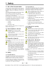
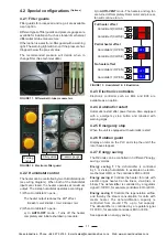
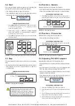
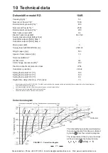
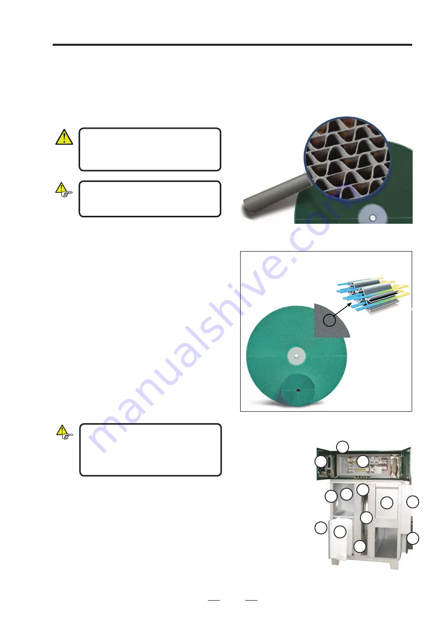
FIGURE 2: Rotor matrix
3 Design
The unit should be electrically isolated
before dismantling. The main switch
should be in position "0", and can be
locked in this position.
If the unit has been in operation, wait until
the regeneration fan has stopped before
disconnecting and dismantling the unit.
The unit is designed so that it easily can
be lifted by a fork lift. To allow securing
of the unit to the floor or to a pedestal,
square washers are delivered with the
unit.
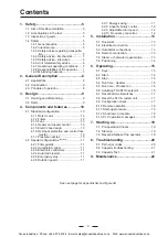
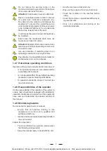
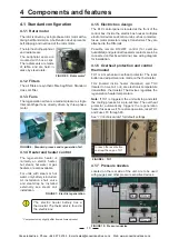
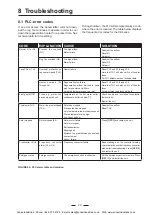
1. Electric equipment
2. Rotor
3. Rotor motor
4. Reg filter
5. Process filters
6. Process fan
7. Reg. fan, behind
electric cabinet
8. Regen. heater
9. Process air in
10. Dry air out
11. Regen. air in
12. By-pass
13. Wet air out, behind
electric cabinet
1
2
6
10
11
3
8
7
5
9
12
4
13
Section of a dehumidifier rotor from Seibu Giken.
The high number of channels means that mois-
ture is adsorbed with extra
efficiency!
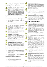
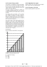
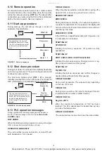
FIGURE 3: Principle function of the rotor
FIGURE 4: Principle of design
high capacity for adsorbing water vapour. It has a
galvanized sheet metal lining, spokes and a hub and
two bearings on which it rotates around a fixed steel
shaft.
3.1 Housing and dismantling
The RECUSORB RZ dehumidifier has a housing
of galvanized sheet metal (AlZn). The unit housing
contains rotor, rotor motor with belt transmission,
regeneration heater and filters. The fans and the
electrical control equipment are placed externally on
the unit.
The regeneration fan removes residual heat from the
regeneration heater for ten minutes after the unit has
been switched off.
The access panel at the front of the unit can easily be
opened, to enable service and inspection. The panels
can be opened without any tools as they are fixed with
hand wheels.
The rotor unit is located between the two panel doors
at the front. It contains rotor, rotor transmission and
rotor motor. The short side of the rotor unit has a
polycarbonate access panel, which is screwed to the
rotor unit. The panel is removed to gain access to the
rotor and the rotor transmission. The rotor motor can
be reached when the left hand panel door is opened.
The electric box with control panel and all electric
equipment is located on the top of the unit. The lids
of the electric box can be opened when the lock are
turned with a key that is attached with the unit.
The air connections are round galvanized spigots in
standard dimensions.
3.2 Rotor
The heart of a DST dehumidifier is the very efficient
patented SSCR silica gel rotor. The rotor matrix
is manufactured from alternate layers of flat and
corrugated sheets of silica gel and metal silicates,
chemically bonded into a tissue of inorganic fibres. It
is made to form a vast number of axial air channels
running parallel through the structure. The large
internal surface area combined with the special micro
structure of the SSCR silica gel material, ensures
maximum contact area to give the rotor an extremely
Cooke Industries - Phone: +64 9 579 2185 Email: sales@cookeindustries.co.nz Web: www.cookeindustries.co.nz


