SLICE User’s Manual
July 2017
support.dtsweb.com
29
Version 1.0i
The status LED is red, green or blue. At system power up, the LED cycles from red to
green to blue followed immediately by the power LED boot-up sequence.
The status LED indicates communication and arm status.
•
When the unit is not armed, the status LED will blink green when handling a
command from the PC.
•
For Recorder Mode
o
When the unit is first armed, the LED will go solid blue to indicate that it
is waiting for the START RECORD signal but not taking data.
o
When it receives the START RECORD signal, the LED will turn green to
indicate that it is actively recording data.
o
The LED will turn off when data collection has completed.
o
If an EVENT signal is received while the unit is recording data, the LED
will turn red and then turn off when data collection has completed.
•
For Circular Buffer Mode
o
When the unit is armed, the LED will go solid green to indicate that it is
collecting data and waiting for the EVENT signal.
o
When an EVENT signal is received the LED will turn red and then turn off
when data collection has completed.
6.2.
Power (PWR) LED
Action
Result
(not armed)
Power up
Connected to USB power Only
Connected to external power
–
power is OK
Connected to external power
–
power is low
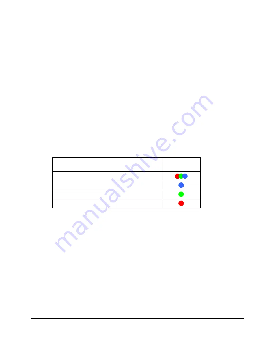
The power LED is red, green or blue.
•
At power up, the LED cycles from red to green to blue immediately after the
status LED has completed its boot-up sequence.
•
When USB is connected, the LED will turn blue.
•
With OK external power, the LED will turn green.
•
With low external power, the LED will turn red.
•
These transitions do not happen if the unit is armed.
Summary of Contents for SLICE MICRO
Page 41: ...APPENDIX E SLICE Grounding Recommendations...
Page 47: ...APPENDIX F SLICE Bridge Sensor Connections...
Page 64: ......


