


A
B
C
D
A
B
C
D
8
7
6
5
4
3
2
1
8
7
6
5
4
3
2
1
MDL:
DTS_SLICE6
DRW:
DTS_SLICE6
DATE:
SEAL BEACH, CA 90740
562-493-0158
www.dtsweb.com
MATERIAL:
UNLESS OTHERWISE SPECIFIED:
UNITS = MM [INCH]
DIMENSIONAL TOLERANCES .254 [0.010"]
INTERPRET PER ASME Y14.5. DO NOT SCALE.
SCALE:
SIZE:
SHEET:
DRAWN:
DTS P/N:
DESCRIPTION:
REV:
1 OF 2
This drawing contains information that is the property of Diversified Technical Systems, Inc. (DTS).
All copyright, patent, and ownership rights are retained. This information shall not be disclosed,
reproduced in whole or in part, or used for manufacture without prior written consent from DTS.
INTELLECTUAL PROPERTY STATEMENT
REV ZONE DESCRIPTION DATE BY
B
2,4
.094[
]
0
.000[
]
21,6
.850[
]
30
1.181[
]
32,05
1.262[
]
2,4 .094
[
]
0 .000
[
]
21,6 .850
[
]
24 .945
[
]
CONN
13,5 .531
[
]
3,25
.128[
]
0
.000[
]
(4X) R1 [.039]
2X R0,5 [.020]
(2X) 2,7 [.106] .005" THRU
MOUNT USING (2X) M2.5 SCREWS
TORQUE TO 1.2 N-M CLEAN & DRY
1,05 [.041]
+0.000 -0.005"
CONN
6,8
.268[
]
0
.000[
]
10,5
.413[
]
.015"
13
.512[
]
CONN
2
.079[
]
0
.000[
]
22,7
.894[
]
1,3
.051[
]
0
.000[
]
1,3 .051
[
]
0 .000
[
]
22,7 .894
[
]
9,2 .362
[
]
0 .000
[
]
CONN
12 .472
[
]
Pin
Signal
1
-
2
+EXCIT-CH4
3
+SIG-CH4
4
-SIG-CH4
5
-EXCIT-CH4
6
+EXCIT-CH1
7
+SIG-CH1
8
-SIG-CH1
9
-EXCIT-CH1
10
+ID-CH4
11
-ID-CH4,5,6
12
+ID-CH1
13
-ID-CH1,2,3
14
+EXCIT-CH5
15
+SIG-CH5
16
-SIG-CH5
17
-EXCIT-CH5
18
+EXCIT-CH2
19
-
20
+SIG-CH2
21
-SIG-CH2
22
-EXCIT-CH2
23
+ID-CH5
24
+ID-CH2
25
+EXCIT-CH6
26
+SIG-CH6
27
-SIG-CH6
28
-EXCIT-CH6
29
+EXCIT-CH3
30
+SIG-CH3
31
-SIG-CH3
32
-EXCIT-CH3
33
+ID-CH6
34
+ID-CH3
35
TEMP-VDC
36
Earth (GND)
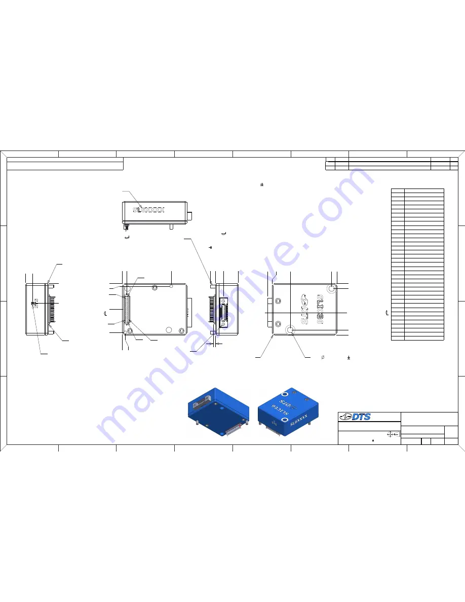
SLICE6 DAS,
MOUNTING DRAWING
2
G NEWTON
2016-09-20
2:1
2
P/N, DRAWING FORMAT
2017-08-28 GN
6061-T6 ALUMINUM HOUSING
W/ BLUE ANODIZE
NOTES:
1. MASS: 15 GRAMS 3 GRAMS
2. SLICE6 SENSOR CONNECTOR: OMNETICS P/N A79047-001 (NSD-36-DD-GS)
MATES WITH: OMNETICS P/N A79046-001 (NPD-36-DD-GS)
3. SLICE6 CHAIN CONNECTOR: OMNETICS P/N A29100-021 (MNSO-21-AA-N-ETH-M)
SENSOR CONNECTOR
PIN ASSIGNMENTS
P1
P19
P36
P20
SENSOR CONNECTOR
(2X) M1.5 DOWEL PINS
CHAIN CONNECTOR
SERIAL NUMBER
PREFIX: SL6
STATUS LED
CONNECTOR
SEALING GASKET
Summary of Contents for SLICE6 DAS
Page 20: ......


