background image


7


2.


Pack


Contents


Thank


you


for


purchasing


the


Ducar®


4


Stroke


Petrol


Engine


Powered


Tiller.


When


you


open


your


packaging,


first


remove


all


items


and


check


there


are


no


parts


damaged


or


missing.


If


you


find


anything


wrong,


do


not


operate


the


product


until


the


parts


have


been


replaced


or


the


fault


has


been


rectified.


Failure


to


do


so


could


result


in


serious


injury.


IMPORTANT


INFORMATION


NOTE:


This


product


is


a


4


stroke


engine


powered


Tiller.


The


engine


MUST


be


filled


with


recommend


SAE


10W/30


BEFORE


starting.


Fresh


unleaded


fuel


must


be


used


in


this


unit.


DO


NOT


use


Ethanol


based


fuels.


DO


NOT


mix


oil


with


fuel.


NOTE:


Inexperienced


or


first


time


users


pay


particular


attention


to


the


operation


of


the


Tiller,


including


details


of


starting


and


stopping


the


tiller


and


correct


use.


Contents


of


carton


1


x


Tiller


main


body


1


x


handle


bar


2


x


mud


fender


1


x


drag


bar


1


x


drag


bar


hairpin


2


x


blade


assembly


1


x


handle


bar


adjuster


1


x


handle


bar


mounting


cover


2


x


cable


clips


6


x


mud


fender


assembly


(M8x16


bolt+

Φ

8


M8


nut)


4


x


mud


fender


support


M6x16


bolt


and


M6


nut


1


x


M5x20


bolt


2


x


ST4.8x16


bolt


2


x

Φ

8x40


wheel


locking


pin


2


x


wheel


hairpin


1


x


locking


pin


for


connecting


bar


1


x


hairpin


for


connecting


bar


Summary of Contents for DT36V

Page 1: ...efully necessary Or ure is just fo y the user y informati iginal inst or your refe manual wh on for pro O tructions erence hich has be oper use G Opera een purpos incompl Gasolin tor s M ely drawn ian...

Page 2: ......

Page 3: ...igned to g erstand the ny s tiller operation a n available s without ad ermanent p eceded by t hazard with a hazard wi hazard with uestions ab give safe an e Owner s and mainten at the tim dvance not...

Page 4: ...lo of Purch el Numb Number Numbe SAVE manual con enance owing inform hase er r r E THIS M ntains impo mation bell MANUA ortant infor low for serv AL FOR rmation reg vice or warr FUTUR garding saf rant...

Page 5: ...2 Pack Contents 7 3 Component Identification 8 4 Assembly 10 5 Pre operation Check 11 6 Engine Start 3 7 Tiller Operation 14 8 Stopping 176 9 Maintenance 17 10 Transporting and Storage 20 11 Troubles...

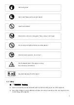
Page 6: ...vide adequate ventilation When installing ventilated protection is to be observed The rotating parts are sharp and running at high speed Accidental contact can cause serious injury Keep your hands and...

Page 7: ...ot components Do not touch Risk of catapulted parts if the engine is running Be sure to keep a safe distance Keep bystanders away from the device 1 2 Safety 1 WARNING Training a Read the instructions...

Page 8: ...rol vapors have dissipated Replace all fuel tank and container caps securely d Replace faulty silencers e Before using always visually inspect to see that the tools are not worn out or damaged Replace...

Page 9: ...fety covers Fan cover recoil starter cover are in place Know how to stop the engine and tines quickly in case of emergency Understand the use of all controls Keep a firm hold on the handlebars they ma...

Page 10: ...ow the engine to cool down before performing maintenance or storing the tiller indoors 1 7 Carbon Monoxide Poisoning Hazard Exhaust contains poisonous carbon monoxide a colorless and odorless gas Brea...

Page 11: ...f earth can be caught by the hoeing assembly and thrown out If foreign bodies e g stones are encountered by the hoeing device stop the machine switch it off and check it for damage Do not work on any...

Page 12: ...g Fresh unleaded fuel must be used in this unit DO NOT use Ethanol based fuels DO NOT mix oil with fuel NOTE Inexperienced or first time users pay particular attention to the operation of the Tiller i...

Page 13: ...tch Clutch cable Engine spee Engine spee Drag bar Mud fender Blade assem Gear box Front wheel Recoil starte Fuel tank ca Air filter onent Id ch lever e ed adjustmen ed adjustmen mbly er p dentifica t...

Page 14: ...eck if all the components are in readiness and not broken 4 1 Lift front wheel Pull the front wheel downward so that the front wheel can rotate freely then lift the front wheel bracket to a proper pos...

Page 15: ...mium quality 4 stroke engine oil certified to meet or exceed U S automobile manufacturer s requirement for API Service Classification SG SF CAUTION Using non detergent oil or 2 stroke engine oil could...

Page 16: ...ot to spill fuel when refueling Spilled fuel or fuel vapor may be ignited If any fuel is spilled make sure the area is dry before starting the engine Avoid repeated or prolonged contact with skin or b...

Page 17: ...6 2 Pull the starter grip lightly until resistance is felt then pull rapidly CAUTION Do not allow the starter grip to snap back against the engine Return it gently to prevent damage to the starter 6...

Page 18: ...ith a hitch pin The tilling depth adjustment can be made as follows Remove the hitch bar locking pin sliding the drag bar up or down as necessary 7 3 Clutch operation The clutch engages and disengages...

Page 19: ...the turn This will permit a turn with relative ease CAUTION Do not use the tiller with a rotor with diameter over 260mm Operating the tiller on grades could cause the tiller to tip over Allowing any o...

Page 20: ...ergency Turn the engine switch chock lever to STOP position In normal use Release the clutch lever to DISENGAGED position and let chock lever to STOP position 1 Disengage the clutch 2 Turn the chock l...

Page 21: ...aintenance Schedule REGULAR SERVICE PERIOD ITEM Daily First month or 20 Hrs Every 3 months or 50 Hrs Every 6 months or 100 Hrs Every year or 300 Hrs Engine oil Check level O Change O O Air cleaner ele...

Page 22: ...explosion could result in CAUTION Never run the engine without air cleaner or rapid engine wear will be the result 1 Remove the wing nut and the air cleaner cover Remove the elements and separate the...

Page 23: ...Measure the plug gap with a feeler gauge The gap should be 0 7 0 8mm 0 028 0 031 in Correct as necessary by bending the side electrode 4 Attach the plug washer thread the plug in by hand to prevent cr...

Page 24: ...buretor by loosening the drain knob Drain the gasoline into a suitable container 3 Pull the starter grip until resistance is felt Continue pulling until the notch on the starter puller aligns with the...

Page 25: ...e Possible Causes Solution Clutch not work Engine speed is low Open throttle increase engine speed Belt too long Replace Spring failure Replace Bearing inside gearbox failure Replace Sliding Spring Be...

Page 26: ...ainty K 2 Workstation sound pressure level dB A 74 Guaranteed sound power level dB A 93 Measurement uncertaintyK 2 Gear shifting NA Model DVO160 Type 1 cylinder 4stroke OHV forced air cooling Bore X s...

Reviews: