background image

2

3

ENGLISH

L2003212  Installation guide for DucoBox Energy Comfort (Plus) (Revision A  |  18.10.2022)

01 

Introduction

The DucoBox Energy Comfort (Plus) is a mechanical ventilation unit 

with heat recovery� It supplies fresh air mechanically to and extracts 

contaminated air mechanically from the house by means of built in 

fans� During this process, the heat is recovered from the extracted air 

and transferred to the air supplied�

The DucoBox Energy Comfort (Plus) is a functional product and re-

quires to be fitted by a professional installer�

A mechanical ventilation unit with heat recovery consists of:

•  The unit

•  Ducting systems to take in outdoor air

•  Ducting systems to exhaust stale air to the outside

•  Duct system for supplying fresh preheated air indoors

•  Ducting systems to extract stale indoor air to the unit

•  Supply vents/grilles to supply the preheated air into dry rooms

1

•  Exhaust vents/grilles to extract the stale air from wet rooms

2

1�   Dry rooms: living rooms, bedrooms, etc�

2�   Wet rooms: kitchen, bathroom, toilet, etc�
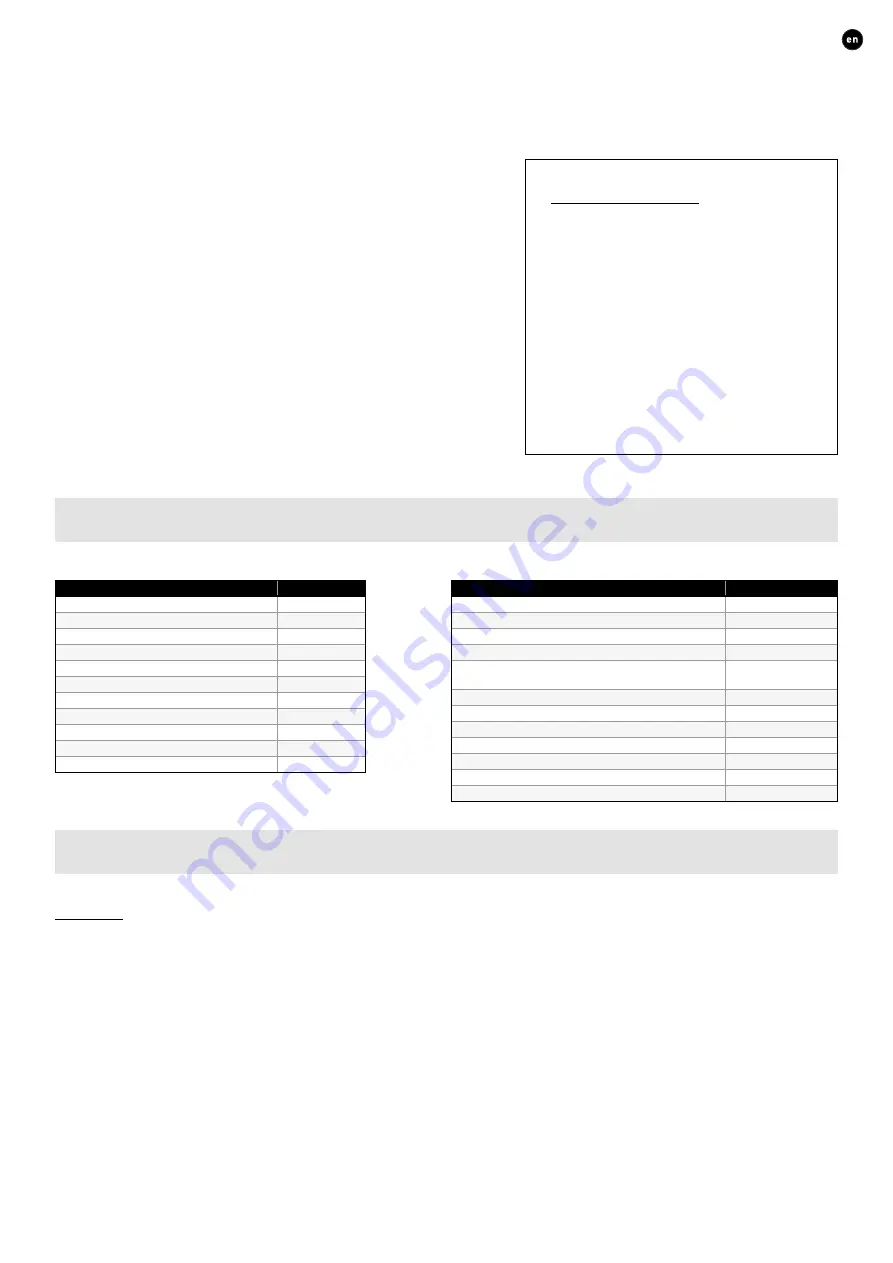
01.A 

Versions

Unit

Product

Article number

DucoBox Energy Comfort D225

0000-4655

DucoBox Energy Comfort D325

0000-4649

DucoBox Energy Comfort D325 Perilex

0000-4659

DucoBox Energy Comfort D325 UK

0000-4658

DucoBox Energy Comfort D400

0000-4707

DucoBox Energy Comfort D400 UK

0000-4757

DucoBox Energy Comfort Plus D350

0000-4704

DucoBox Energy Comfort Plus D350 UK

0000-4758

DucoBox Energy Comfort Plus D450

0000-4705

DucoBox Energy Comfort Plus D450 UK

0000-4759

DucoBox Energy Comfort Plus D550

0000-4706

Optional accessories

Product

Article number

Siphon flat (Energy & Eco)

0000-4376

Communication Print WIFI

0000-4810

Humidity Sensor DucoBox Energy Comfort (Plus)

0000-4723

Mounting Chair Standing (Energy Comfort 325)

0000-4546

Mounting Chair Standing (Energy Comfort (Plus)/Pre-

mium)

0000-4740

Multi-zone valve DucoBox Energy Sensorless D125

0000-4761

Multi-zone valve DucoBox Energy Sensorless D160

0000-4760

Pre-Heater DucoBox Energy Comfort (Plus)

0000-4807

Connection piece with rubber D160/D160 (M/M)

0000-4724

Connection piece with rubber D180/D160 (M/M)

0000-4725

Connection piece with rubber D180/D180 (M/M)

0000-4726

Connection piece with rubber D200/D180 (M/M)

0000-4727

01.B 

Operation

Bypass

The bypass ensures, should it be necessary, that there is no heat transfer between air extracted and supplied� This means that the 

house cools down in a controlled and gradual manner� This function is active mainly in the summer� The bypass opens if the indoor 

temperature rises above the set comfort temperature (set to 21.5 °C by default) and the outdoor temperature is above 10 °C
As the comfort temperature in the sleep zone and the day zone can be different, it is possible to define different comfort tempera-

tures in zone-controlled systems, e�g�: 21�5° for the day zone and 18° for the night zone�
The unit contains 2 bypasses� Either only the right-hand bypass or only the left-hand bypass will serve, depending on the selection 

of L or R in the initial installation screen� The software will always close the non-selected bypass�

Scope of supply

Before starting to install the heat recovery 

unit, check to ensure it is complete and 

undamaged�

The scope of supply of the DucoBox Energy 

Comfort (Plus) type heat recovery unit 

comprises the following components:

•  DucoBox Energy Comfort (Plus)

•  Fixing bracket

•  Installation guide

•  User manual

•  2 x DucoBox Energy Comfort (Plus) 

Filter 

ISO 16890 Coarse 65 % (�≈ G4)

Summary of Contents for 0000-4649

Page 1: ...Installation guide ENGLISH DucoBox Energy Comfort Plus L2003212 Revision A 18 10 2022...

Page 2: ...A DucoBox Energy Comfort Plus start up 20 07 Electrical installation 22 07 A Pairing components 22 07 B Removing replacing components 23 07 C Tips 24 08 Air side calibration 25 08 A Presetting vents 2...

Page 3: ...Communication Print WIFI 0000 4810 Humidity Sensor DucoBox Energy Comfort Plus 0000 4723 Mounting Chair Standing Energy Comfort 325 0000 4546 Mounting Chair Standing Energy Comfort Plus Pre mium 0000...

Page 4: ...written permission 0 000 Weight Outline Format A2 Mat Tol DucoBox Energy Comfo 680 705 700 500 540 175 120 175 120 255 125 190 385 125 125 385 190 160 160 160 1 6 0 597 235 509 610 345 21 Nov 19 In Wo...

Page 5: ...0 55 17 AM In Work Status Date Status A1176500 HANDELSSTRAAT 19 8630 VEURNE BELGIUM tel 0032 58 330033 fax 0032 58 330044 info duco eu www duco eu This drawing is property of Vero Duco NV and can not...

Page 6: ...alcohol insecticides petrol etc Make sure that the electrical system to which the unit is connected complies with the stipulated conditions Do not expose the device to weather conditions Do not place...

Page 7: ...uced physical sensory or mental capabilities or who lack experience of know how unless they are supervised or have been given instructions on the use of the unit by a person who is re sponsible for th...

Page 8: ...cover 17 Air filter Coarse 65 G4 8 Air filter cover 18 Condensate drain connection 9 Bypass valve 19 Condensate drain connection 10 Power cable 230 VAC 20 Sheet metal Plus variants only 21 Nov 19 Rel...

Page 9: ...l Communication Print WIFI you have the option of allowing the DUCO ventilation systems to communicate via WIFI and or ethernet Additionally a ModBus TCP IP protocol has been developed to enable commu...

Page 10: ...230 VAC User controller POWER SUPPLY Max of 50 components of which no more than 25 RF RF obstacle free zone at least 30 cm Min 0 75 mm 230 VAC 24 VDC Duco Reference POWER SUPPLY 24 VDC 230 VAC Duco W...

Page 11: ...d on the PCB D400 and Plus variants mounted transformer 04 C Connecting cables to the PCB Loosen the screws Slide the cap forwards Cut off one or more of the provided pieces from the housing to connec...

Page 12: ...distance 350 m free field less through obstacles Maximum number of components Up to 25 wireless components in a single system 04 F Wired cabled communication Wired components can be daisy chained rec...

Page 13: ...mmer months Ensure that the air inlet is accessible for any cleaning that may be required A smaller passage area can actually have a major negative impact on system performance DUCO recommends install...

Page 14: ...e it has been hung The unit must be mounted vertically against a solid wall with a minimum mass of 200 kg m for a vibration free suspension Gypsum blocks or metal studs do not suffice The type of cond...

Page 15: ...operly 05 C Humidity Sensor optional The optional separately available Humidity Sensor 0000 4723 is placed in the extract air duct of the DucoBox Energy Comfort Plus and centrally measures the humidit...

Page 16: ...nnectors with rubber to the ventilation unit The 4 connection noz zles on the ventilation unit have a diameter of 160 F for DucoBox Energy D225 D325 and 180 F for all other versions Choice of connecto...

Page 17: ...or Air Supply air from outdoors to the unit ETA Extract Air Supply air from the house to the unit EHA Exhaust Air Exhaust air from the unit to outdoors 05 E External multi zone valves optional Mountin...

Page 18: ...eater The Pre Heater is mounted in the ducts with outdoor air supply ODA The part is provided with 2 connection openings 180 F Depending on the duct diameter used the appropriate connection pieces see...

Page 19: ...FROST PROTECTION HEATER EXT 05 G Vents You should preferably use DUCO vents such as DucoVent Basic or DucoVent Design See the technical data sheet or fitting instruc tions for the DucoVent Basic or De...

Page 20: ...IGHT HAND setting The display shows the correct position in relation to the selected setting LEFT HAND setting RIGHT HAND setting Condensate drain RIGHT Condensate drain LEFT Standard siphon Iteration...

Page 21: ...s it is space saving and less likely to cause air leaks It can be fitted dry and it has the advantage that it cannot dry out in hot weather Next steps After this you can proceed to the next steps to f...

Page 22: ...room toilet kitchen laundry room Briefly tap any button of all components to be paired The LED on the component will start flashing green once it has been paired correctly The number of paired compone...

Page 23: ...tion in progress White Normal operation The brightness of the LED on the DucoBox and some control components indicate the current ventilation percentage bright 100 ventilation Blue Component is displa...

Page 24: ...ch buttons The LED will turn white 07 C Tips The network can be wiped or a full reset of the DucoBox Energy Comfort Plus can be carried out in the event of any problems To do this refer to the followi...

Page 25: ...ended for supply vents in order to prevent excessive noise from being generat ed For this reason it is recommended that the flow be split between different vents for higher flow rates SITUATION 1 One...

Page 26: ...nd resistance and using a pressure compensated air flow meter measure the flow rate at this vent If the flow rate is too high or too low you can adjust it using the arrow keys on the DucoBox Energy Co...

Page 27: ...on procedure The other unit will take over the calibration settings of the first unit by copying the calibration code Copying the calibration data to another unit 1 Make sure that all valves are adjus...

Page 28: ...1 minute Press any button at random on the display in order to reactivate it Press enter to retrieve the menu Main screen The display will light up continuously when the DucoBox Energy Comfort Plus s...

Page 29: ...sing the arrow keys will enable changing the ventilation position Open the menu via enter The selected ventilation position on the unit is permanent indicated in purple in Controls until the user acti...

Page 30: ...across the heat exchanger or not at all Fresh outdoor air will therefore not be heated up by warm stale indoor air This relatively cooler outdoor air entering the house will be used to reduce the tem...

Page 31: ...cates that the advanced mode is active The menu will exit the advanced mode after 30 minutes of inactivity or after restarting the DucoBox Energy Comfort Plus The advanced mode can also be closed down...

Page 32: ...d set parameters of the nightboost function BUILDING TYPE Selection of the parameter HOUSE landed or FLAT non landed INFO TEMPERATURE SENSORS for information The DucoBox Energy Comfort Plus features 4...

Page 33: ...of the unit The messages can be consulted via the display menu INFO ERROR LIST An overview of codes and related actions can be found on the website www duco eu Via the display menu under SETTINGS CONF...

Page 34: ...ted Dynamic Airflow filters have a beneficial impact on efficiency and power input These must always be placed correctly in the unit by matching the L and R icons marked both on the filter and on the...

Page 35: ...complaints are to be reported to DUCO by the DUCO distributor with a clear description and the order invoice number under which the products were delivered To do so please fill out the complaint regi...

Page 36: ...Installed by L2003212 Document last modified on 18 10 2022 revision A...

Reviews: