background image

4

IT IS NECESSARY THAT ALL THE OPERATIONS REGARDING THE INSTALLATION, ADJUSTMENT 

AND ADAPTATION TO THE TYPE OF GAS AVAILABLE ARE CARRIED OUT BY QUALIFIED 

PERSONNEL, IN CONFORMITY WITH THE REGULATIONS IN FORCE.

THE SPECIFIC INSTRUCTIONS ARE DESCRIBED IN THE BOOKLET SECTION 

INTENDED FOR THE INSTALLER

INSTRUCTIONS FOR THE USER

The symbols silk-screen printed on the side of the 

knob indicate the correspondence between the 

knob and the burner.

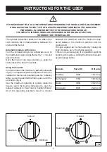
Automatic start-up with valves

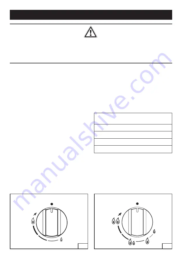
Turn the corresponding knob anticlockwise up to 

the maximum position (large flame, fig.1 - 1/A) and 

press the knob.

Once the burner has been started up, keep the 

knob pressed for about 5 seconds.

Using the burners

In order to obtain the maximum yield without waste 

of gas, it is important that the diameter of the pot is 

suitable for the burner potential (see the following 

table), so as to avoid that the flame goes out of the 

pot bottom (fig.2).

Use the maximum capacity to quickly make the 

liquids reach the boiling temperature, and the 

reduced capacity to heat food or maintain boiling. 

All of the operating positions must be chosen 

between the maximum and the minimum ones, 

never between the minimum position and the 

closing point.

The gas supply can be interrupted by turning the 

knob clockwise up to the closing position.

If there is no power supply, it is possible to light the 

burners with matches, setting the knob to the start-

up point (large flame).

Burners 

Power W 

Ø of pots

Auxiliary 

1000 

10-14 cm

Semi-rapid 

1750 

16-18 cm

Rapid 

3000 

20-22 cm

Ultra-rapid 

4000 

22-24 cm

1

Closed

Maximum

Minimum

1/A

Closed

Maximum

Minimum

Summary of Contents for G02-M1

Page 1: ...We are sure that this new appliance manufactured with quality materials will meet your requirements in the best possible way The use of this new equipment is easy However we invite you to read this b...

Page 2: ...nd the gas equipment Insufficient ventilation produces a lack of oxygen In case of an intense or prolonged use of the equipment it may be necessary to improve aeration for example by opening a window...

Page 3: ...3 DESCRIPTION AND DIMENSIONS 1 Rapid burner 3000 W 2 Semi rapid burner 1750 W 3 Auxiliary burner 1000 W 4 Ultra rapid burner 4000 W 5 Ultra rapid burner 2 way 4000 W 6 Control Knob for burner 5 6 5...

Page 4: ...btain the maximum yield without waste of gas it is important that the diameter of the pot is suitable for the burner potential see the following table so as to avoid that the flame goes out of the pot...

Page 5: ...e electric grid Don t use a steam cleaner for the cleaning the hob It is advisable to clean the appliance when it is cold Glass platform and enamelled parts The glass platform and all of the enamelled...

Page 6: ...appliance is designed to be embedded into heat resistant pieces of furniture The walls of the pieces of furniture must resist a temperature of 65 C besides the room one The equipment must not be insta...

Page 7: ...7 CUT OUT DIMENSIONS 800 400 370 760 75...

Page 8: ...in conformity with the local regulations Gas connection Make sure that the appliance is adjusted for the gas type available see the label under the appliance Follow the instructions indicated in the c...

Page 9: ...ight spanner L unscrew the nozzle U1 U2 fig 7 B and substitute it with the corresponding one Tighten the nozzle strongly Adjusting the burners The lowest flame point must always be properly adjusted a...

Page 10: ...lder and screw down the cap T 9 TECHNICAL CHARACTERISTIC TABLES BURNERS GAS NORMAL PRESSURE NOMINAL RATE INJECTOR DIAMETER TAPE BY PASS DIAMETER NOMINAL HEAT INPUT W N DESCRIPTION mbar g h 1 100 mm 1...

Page 11: ...l recycling treatment and environmentally friendly disposal helps reduce possible negative effects on the environment and health and also enables the materials making up the product to be recycled For...

Reviews: