background image

- C 38 -

Short Seam Automat 2211-5 Working Instructions

Beisler Automated Sewing Equipment

Section C

Service Instructions

Contents

C.1 Delivery of the machine .................................................................................................... 39

C.1.1

Packaging .................................................................................................................... 39

C.1.2

Scope of delivery ......................................................................................................... 39

C.2 Storage and location requirements ................................................................................. 40

C.2.1

Floor quality ................................................................................................................. 40

C.2.2

Interior climate ............................................................................................................. 40

C.2.3

Floor space required ................................................................................................... 40

C.2.4

Supply connections ..................................................................................................... 40

C.3 Start-up ............................................................................................................................... 41

C.3.1

Machine table alignment ............................................................................................. 41

C.3.2

Compressed air  / vacuum connections ...................................................................... 42

C.3.3

Connecting the machine to the power supply ............................................................. 43

C.3.4

Safety check ................................................................................................................ 43

C.4 Operation and shut-down ................................................................................................. 44

C.4.1

Working with the machine ........................................................................................... 44

C.4.2

Machine shut-down ..................................................................................................... 44

C.5 Maintenance ....................................................................................................................... 45

C.5.1

Inspection .................................................................................................................... 45

C.5.2

Cleaning ...................................................................................................................... 45

C.5.3

Service ......................................................................................................................... 46

C.5.4

Repairs ........................................................................................................................ 47

Operating panel replacement ................................................................................. 47
Clamp transport belt replacement .......................................................................... 48
Clamp rail replacement ........................................................................................... 49
Cutter replacement ................................................................................................. 49
Cutter block replacement ........................................................................................ 49
Assistance transport belt replacement ................................................................... 50
Pin assignment step motor ..................................................................................... 50
Assistance transport stamp pressure adjustment .................................................. 51

C.5.5

Machine set-up ............................................................................................................ 52

Guide laser adjustment ........................................................................................... 52
Clamp rail clamping pressure adjustment .............................................................. 53
Adjustment of the clamp slide disengagement position ......................................... 54
Adjustment of the clamp rail parallel orientation .................................................... 54
Folder to clamp rail alignment ................................................................................ 55
Folder lower position adjustment ............................................................................ 56
Folder to pick-up plate alignment ........................................................................... 57
Folder bar to folder clamp alignment ...................................................................... 58
Right slash selvage stop alignment ........................................................................ 59
Cutter adjustment .................................................................................................... 60
Photocell light sensitivity setting ............................................................................. 61
Adjustment PCB  stepper motor ............................................................................. 62
Setting the thread cutter ......................................................................................... 63
Checking the rest thread monitor ........................................................................... 64

C.6 Troubleshooting ................................................................................................................ 65

C.7 Specifications .................................................................................................................... 68

Summary of Contents for 2211/5

Page 1: ... A 1 Short Seam Automat 2211 5 Working Instructions Beisler Automated Sewing Equipment Working Instructions Short Seam Automat 2211 5 ...

Page 2: ...etting up and service of the machine D Programming instructions page D 69 D 103 Instructions for the service personnel in charge of preparing and setting up the machine Scope of the working instructions These working instructions describe the SHORT SEAM AUTOMAT 2211 5 of Beisler GmbH and apply only to those machine parts and components that are contained in the scope of delivery of the SHORT SEAM ...

Page 3: ... A 3 Short Seam Automat 2211 5 Working Instructions Beisler Automated Sewing Equipment SectionA General notes ...

Page 4: ...uctions A 4 Beisler Automated Sewing Equipment SectionA General notes Contents A 1 Safety instructions 5 A 1 1 Symbols used in the working instructions 8 A 1 2 Symbols used on the machine 8 A 1 3 General safety instructions 9 A 2 Notices 10 ...

Page 5: ...f the working instructions are subject to change without further notice Concerning translations into foreign languages the German version of these working instructions is binding Should you encounter problems that are not mentioned in these working instructions please contact your supplier immediately for your own safety Please do not hesitate to contact Beisler if you have any suggestions that he...

Page 6: ...GmbH is not responsible for damage that arises from the use of non defined and non approved spare parts or accessories Copyright 2008 Beisler GmbH Hösbach Edition 02 2008 Short seam automat The short seam automat 2211 5 and all related parts are protected by copyright Any reproduction of the machine will be prosecuted Working instructions These working instructions are protected by copyright No pa...

Page 7: ...tial operation of the SHORT SEAM AUTOMAT 2211 5 read the ope rating instructions carefully so that you can make full use of the advantages of the machine and to prevent damage Important information for the service personnel Please note that service work to the SHORT SEAM AUTOMAT 2211 5 must be carried out only by authorized and adequately trained expert personnel Expert personnel means persons tha...

Page 8: ...ns WARNING is used if non observance may cause serious or even lethal injuries CAUTION is used if non observance may cause medium to minor injuries or damage NOTE is used for hints and useful information A 1 2 Symbols used on the machine WARNING DANGER Caution Observe working instructions WARNING HIGH VOLTAGE Caution Prior to opening pull out power plug ...

Page 9: ...rements DIN EN 50178 VDE 0160 1998 04 Equipment of power systems with electronic devices DIN EN 50082 VDE 0839 Part 2 1997 11 Electromagnetic compatibility basic specification immunity to interference Part 1 Domestic business and commerce small enterprises Part 2 Industry DIN EN 60204 DIN VDE 0113 1993 06 Electrical equipment of industrial machines A 1 Safety instructions Safety devices The SHORT ...

Page 10: ...Short Seam Automat 2211 5 Working Instructions A 10 Beisler Automated Sewing Equipment A 2 Notices ...

Page 11: ... B 11 Short Seam Automat 2211 5 Working Instructions Beisler Automated Sewing Equipment Section B Operating Instructions ...

Page 12: ... component 21 B 2 12 Sewing left side pocket trousers component 22 B 2 13 Machine cycle right side pocket 23 B 2 14 Lining up right side pocket at trousers 23 B 2 15 Sewing the left side pocket trousers component 24 B 2 16 Switches 25 B 2 17 Operating panel 26 B 3 Operation 27 B 3 1 Safety instructions for operation 27 B 3 2 Preparing the machine 28 B 3 3 Selecting the sewing program 29 B 3 4 Acti...

Page 13: ...trol k Vacuum pump power supply switch Operating switches g Footswitch for machine operation h Footswitch for slash selvage clamp B 1 1 Functional units All functional units of the SHORT SEAM AUTOMAT 2211 5 are mounted to the height adjustable table frame and freely accessible Transport and sewing unit 1 Transport stamp 2 Linear rail under the cover 3 Sewing head 4 Thread holder 5 Right slash selv...

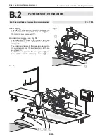
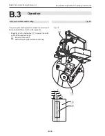
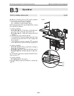
Page 14: ...eft slash selvage to the left trousers component at ladies trousers Sewing of the right slash selvage to the right trousers component at ladies trousers B 2 2 Machine cycle left slash selvage The machine cycle Clipping left slash selvage and sewing it to the left trousers component is performed as follows The left slash selvage is lined up manually at the pick up plate The slash selvage is clipped...

Page 15: ...elvage 3 is lined up at the stop rail 4 of the pick up plate The exact position to the cutter 2 is marked by the gusset in the slash selvage Slash selvage clamp Fig 2 The slash selvage clamp 1 closes and secures the slash selvage 3 while the cloth material is clipped and then crimped over Crimping over and picking up the slash selvage Fig 3 The folder 1 moves right to the pick up plate 2 The slash...

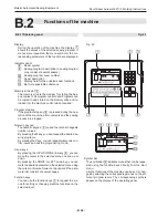
Page 16: ...ne up position of the left trousers component Fig 4 The left trousers component 3 is lined up with the gusset to the cutter 4 and parallel to the red marking line 2 of the guide laser 1 Folder Fig 5 The folder 1 moves left to the working plate with the slash selvage lowers and puts the slash selvage 2 onto the left trousers component 3 Fig 4 5 Fig 4 Fig 5 ...

Page 17: ...e se wing head Sewing head Fig 6 The sewing head 1 only performs the sewing stitch and thread cutting functions All other functions such as seam length or setting the beginning and the end of the seam are acquired by the machine s sensoring system and controlled by the program control in accor dance with the set values Fig 6 Fig 6 Threads Thread stock and thread supply of the sewing head are monit...

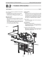
Page 18: ...ng head where it is tucked The finished sewing piece is then blown off the wor king table with compressed air The assistance transport is deactivated B 2 7 Right trousers component line up Ideally the right trousers component is premarked by a gusset If a gusset is not available the line up position is marked with tape or with a felt pen at the working plate or at the pick up plate Folder Fig 7 Th...

Page 19: ... the machine B 2 8 Right slash selvage Stop Fig 9 After the cutter has clipped the stop 1 swivels to the right trousers component Line up position of the right slash selvage Fig 9 The right slash selvage 3 is lined up immediately at the stop rail 2 and flush with the right trousers com ponent Fig 9 Fig 9 ...

Page 20: ... head Sewing head Fig 10 The sewing head 2 only performs the sewing stitch and thread cutting functions All other functions such as seam length and determining the beginning or the end of the seam are acquired by the machine s sen sor system and controlled by the program control in ac cordance with the set values Fig 10 Fig 10 Threads Thread stock and thread supply of the sewing head are monitored...

Page 21: ... up left pocket at trousers component Ideally the side pocket and the left trousers component are premarked by a gusset If a gusset is not available the line up position is marked with tape or with a felt pen at the working plate or at the pick up plate Side pocket line up position Fig 11 The slash selvage clamp is closed during the line up process The cloth ledge 1 of the side pocket 3 is lined u...

Page 22: ... lowers and puts the side pocket 2 onto the left trousers component 3 Main clamp Fig 14 The main clamp 2 moves to the insertion station and picks up the sewing pieces The folder moves up to its start position The main clamp transports the trousers component on the working plate from the insertion station to the se wing head 1 After the sewing process the sewing pieces 4 are blown off the worktable...

Page 23: ...Lining up right side pocket at trousers Ideally the side pocket and the right trousers component are premarked by a gusset If a gusset is not available the line up position is marked with tape or with a felt pen at the working plate or at the pick up plate Side pocket line up position Fig 15 The slash selvage clamp is closed during the line up process The cloth ledge 1 of the side pocket 2 is line...

Page 24: ...s and puts the side pocket 2 onto the right trousers component 3 Main clamp and sewing head Fig 18 The main clamp 2 moves to the insertion station and picks up the sewing pieces The folder moves up to its start position The main clamp transports the trousers component on the working plate from the insertion station to the se wing head 1 After the sewing process the sewing pieces 4 are blown off th...

Page 25: ...the individual ope rating steps of the machine or for starting the fully au tomatic machine operation Footswitch for slash selvage clamp Depressing the footswitch for the slash selvage clamp 4 will open or close the slash selvage clamp indepen dently of the switching state B 2 16 Switches The short seam automat is equipped with three different types of switches Emergency switch for stopping a sewi...

Page 26: ...ions d Bar for requestable submenus Memory stick slot 3 The memory stick is the medium for storing the bak kup copies of all program control data Programs can be copied to and stored on the memory stick and re loaded into the machine control when required Program stop key If the program stop key 6 is pressed during the ope ration of the machine all movements and the sewing process are stopped Nume...

Page 27: ...As moving parts of the machine may catch and wind up loose clothing make sure to stay away from the operating range of the machine to avoid injuries When operating the machine do not wear wide or open clothing Make sure that sleeves are tight fitting and properly closed Handling the guide laser CAUTION Damage of the retina If the eye is directed toward the laser beam for some time the retina may b...

Page 28: ...e required operating pressure of 6 bar by a pressure reducer 3 Check manometer 2 to see if the correct operating pressure is set The pressure reducer is installed at the side mounting wall of the worktable 3 Connect machine to power supply system WARNING Electric shock Contact with current carrying components may cause a lethal electric shock Check plug and cable before connecting machine to power...

Page 29: ... 1 with three different seams 2 The name of the sewing program is M 01 the seams are marked by the seam numbers 01 02 03 Seam 01 is used for clipping and crimping over the left slash selvage and for sewing the left slash selvage to the left trousers component Seam 02 is used for sewing the right slash selvage to the right trouser component Seam 03 is a test seam that is restricted to two func tion...

Page 30: ...er of the activated seam appears blacke ned B 3 5 Deactivating a seam number 1 Select seam number of desired seam Move cursor to seam number Press or Y key Confirm selection Press key The seam number of the deactivated seam is no longer blackened B 3 6 Setting the thread clamp manually Before the first start of a sewing program the top thread clamp must be activated to protect the top thread from ...

Page 31: ... Press key 3 Front working plate cutter right trousers component F Press key 4 Pick up plate cutter left slash selvage right side pocket G Press key 5 Pick up plate cutter left side pocket right slash sel vage at ladies trousers T Taste drücken 6 Load bobbin S Press key B 3 8 Resetting the day counter to zero Use this function to reset the day counter for a program cycle or for a completed working...

Page 32: ...ration B 3 9 Quick stitch width setting The quick stitch width adjustment makes the selection of 4 preadjusted different stitch widths possible Fig 24 Use the handwheel 1 to adjust the stitch width to the required range 2 trousers component 3 slash selvage or prefactured pocket bag Fig 24 Fig 24 ...

Page 33: ...am 19 Right slash selvage for ladies trousers are controlled by using both footswitches The footswitch for the slash selvage clamp 2 closes the slash selvage clamp after the slash selvage has been inserted The footswitch for machine operation 1 controls the entire subsequent process of the sewing programm The sewing programs M 01 with seam 02 Sewing right slash selvage to right trousers component ...

Page 34: ...hes its start position after that the next machine cycle can be started B 3 Operation B 3 11 Start mode 04 05 Start mode for Left slash selvage Left and right side pocket Right slash selvage for ladies trousers The machine cycle Crimping over left slash selvage and sewing to left trousers component can be performed in two different modes Mode 04 Mode 05 Controlling machine cycle in Mode 04 1 Line ...

Page 35: ...in clamp reaches its start position after that the next machine cycle can be started B 3 Operation B 3 12 Start mode 06 07 Start mode for Right slash selvage Left slash selvage for ladies trousers The machine cycle Sew right slash selvage to right trou sers component can be performed in two different mo des Mode 06 Mode 07 Controlling machine cycle in Mode 06 1 Depress footswitch for machine opera...

Page 36: ...ing compressed air blow off dust and thread resi dues at the sewing head at the working plate at the main clamp and at the linear rail B 3 Operation B 3 13 Resetting line up process This function depends on the selected machine cycle mode It only refers to machine movements that can be executed before the start of the automatic process The machine movements can be reset gradually Press key several...

Page 37: ... C 37 Short Seam Automat 2211 5 Working Instructions Beisler Automated Sewing Equipment Section C Service Instructions ...

Page 38: ...rvice 46 C 5 4 Repairs 47 Operating panel replacement 47 Clamp transport belt replacement 48 Clamp rail replacement 49 Cutter replacement 49 Cutter block replacement 49 Assistance transport belt replacement 50 Pin assignment step motor 50 Assistance transport stamp pressure adjustment 51 C 5 5 Machine set up 52 Guide laser adjustment 52 Clamp rail clamping pressure adjustment 53 Adjustment of the ...

Page 39: ...d and aligned the shipping braces must be removed NOTE Damages in transit If any damage presumably caused by incorrect trans port is found when the machine is unpacked please contact your supplier immediately C 1 2 Scope of delivery The machine is delivered in an operative condition The scope of delivery comprises Short seam automat with sewing head The machine is equipped with several customer sp...

Page 40: ...ce of 1 m Machine dimensions L x W x H 1700 x 1200 x 1600 mm NOTE Electromagnetic interference The machine must not be installed in the immediate vicinity of devices or electrical components e g trans formers generating a strong magnetic field as other wise the correct function of the program control may be impaired C 2 4 Supply connections The machine requires on site power and compressed air sou...

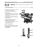
Page 41: ...is equipped with optional transport rollers release bra kes before lifting 2 Fig 2 Loosen lockscrews 2 on all guide rails 3 Pull table legs 3 out to the desired length and retigh ten lockscrews 2 4 Lower machine to floor Horizontal positioning of the machine table 1 Place bubble level onto working plate 2 Fig 2 Loosen table leg lock nuts 1 3 Align machine table horizontally on all sides by raising...

Page 42: ...r clockwise di rection Connecting the machine to the vacuum supply sy stem Fig 4 If the machine is equipped with the optional vacuum pump 3 no further installation is required The vacuum system is ready for operation If the machine is delivered without vacuum pump the on site vacuum source must be connected to the machine s vacuum valve The vacuum valve 5 is mounted below the worktable NOTE Requir...

Page 43: ... ensures free access to and around the machine NOTE Works to the electrical system Works to the electrical system of the machine must only be carried out by qualified and authorized expert personnel Tampering with the machine without au thorization makes the warranty void C 3 4 Safety check Before the machine is released for operation all safety de vices must be checked for their correct operation...

Page 44: ... the two seams 11 and 12 Seam 11 Controls the procedure for sewing the side pocket to the right trousers component Seam 12 Controls the procedure for sewing the side pocket to the left trousers component The standard program M 03 works with the two seams 19 and 20 Seam 19 Controls the procedure for sewing the right slash selvage to the right trousers compo nent at ladies trousers Seam 20 Controls ...

Page 45: ...ected from the power supply system C 5 1 Inspection The machine must be inspected annually The inspection comprises particularly the following items safety devices of the machine operativeness of the program control correct function of inputs and outputs C 5 2 Cleaning The machine must be cleaned after large production se ries or at least once a day whichever occurs first Cleaning the machine surf...

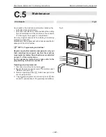
Page 46: ...ises 0 25 l of oil When this oil is used up you can order the special machine oil for service from the manufacturer or supplier of the ma chine Emptying the water separator 1 Disconnect machine from power supply 2 Fig 5 Drain water at pressure reducer water separator into suited container Press button 1 at pressure re ducer collector and keep de pressed until water has been drained completely NOTE...

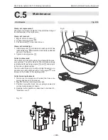
Page 47: ...e held responsible for spare parts from third parties NOTE Programming instructions Repairs require that machine components carry out their individual movements and that the machine movements are tested These functions are controlled on level 1 of the service menu For the necessary instructions please refer to the programming instructions section D Operating panel replacement 1 Disconnect machine ...

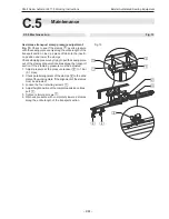
Page 48: ...sion 7 6 Loosen lock nuts 6 of set screws 5 and rotate two set screws backward 7 Fig 8 Remove two connecting screws 1 from main clamp pedestal Remove belt 8 Fig 7 Install new belt to drive roller 1 and to guide roller a 9 Fig 8 The ends of the belt 3 are fitted with holes Position the two ends of the belt with the belt clamp 2 exactly over the holes on the pedestal 4 and secu re them using screws ...

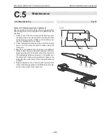
Page 49: ...2 Tighten retaining screw 2 Cutter replacement The cutters are integral to a block together with the pres sure cylinder The cutter block for the left slash selvage is attached with two fixing angles 1 and 2 and screws to the pick up plate bracket The two cutter blocks for the left and right trousers com ponents are each attached with a fixing angle 3 and screws to the bottom of the working plate C...

Page 50: ...5 Remove the retaining screws 8 of the belt clamp 9 Remove belt 6 Install new belt to drive roller 7 and to guide roller 5 7 The ends of the belt are fitted with holes Position the two ends of the belt with the belt clamp 9 exactly over the holes on the holder and secure them using the screws 8 Tension belt by tightening the set screws 4 until the belt can be depressed approx 10 mm with distinct c...

Page 51: ... Check stamping pressure by trying to pull the sewing piece out of the stamps at several locations along the transport section If the stamping pressure must be adjusted 1 Adjust pressure at the pressure reducer 3 to 1 bar 0 1 mpa 2 Check parallel alignment of the stamps 4 to the slide plate of the working plate If the alignment of the stamps must be adjusted 3 Loosen the four retaining screws 1 4 ...

Page 52: ...he line up position of the left and right trousers components parallel to folder and pick up plate The position of the guide laser can be adjusted ver tically and horizontally Adjusting the bracket height 1 Fig 14 Loosen retaining screw 4 at rear of worktable 2 Position laser light bracket 3 in the desired height 3 Tighten retaining screw 4 Horizontal adjustment 1 Loosen lock screw 1 2 Rotate lase...

Page 53: ...he insertion posi tion and lowering the main clamp 2 Check clamping pressure by trying to pull the sewing piece out of the clamp at several locations along the clamp rail 3 Fig 15 If the pressure force is uneven or insufficient remove clamp rail and change the position of the two adjusting screws 1 at the inner side of the clamp rail If the adjusting screws are screwed in the pressure of the clamp...

Page 54: ... be 1 1 5 mm 5 Loosen lock nut 8 of stop screw 7 at pedestal and rotate stop screw to the desired position 6 Check distance A 7 Tighten stop screw lock nut Rear stop point adjustment The rear stop point is adjusted correctly if the clear length B of stop screw 6 measures exactly 10 mm 1 Fig 16 Loosen lock nut 5 of stop screw 6 and ro tate stop screw to the desired position 2 Check length B 3 Tight...

Page 55: ...its entire length Folder position adjustment 1 Move main clamp to position using input output con trol functions Lower main clamp 2 Move folder to position using input output control func tions Rotate folder Close folder clamp Lower folder 3 Fig 18 Check parallel alignment of folder clamp 3 to clamp rail 4 To change the folder clamp alignment 4 Loosen lock screw 1 5 Rotate folder clamp bracket 2 t...

Page 56: ...selvage oder prefactured pocket bag can be presetted Folder lower position adjustment 1 Fig 19 Adjust stop screw 4 at revolver 2 for setting lower folder position Loosen stop screw lock nut 3 at bracket and rotate stop screw 4 to the desired po sition 2 Check distance between folder 8 and clamp rail 7 NOTE Check folder lower position When positioned correctly the folder must lower to the working s...

Page 57: ... Fasten pick up plate by rotating handwheel 4 completely to minus range 2 Move folder 2 to pick up plate 3 using input output control functions Move folder to right Lower folder 3 Adjust pick up plate inclination so that the folder lies absolutely evenly on the pick up plate by loosening the two retaining screws 7 of the pick up plate bracket 5 on the worktable underside and rotate the bracket at ...

Page 58: ...hat the folder can crimp over the left slash sel vage evenly the folder clamp 1 must be positioned cen trically above the folder bar 2 Folder bar adjustment 1 Fig 21 Fasten pick up plate by rotating handwheel 3 completely to minus range Loosen retaining screw 4 of folder bar bracket at the worktable underside and reposition bracket 5 2 Tighten retaining screw Fig 21 Fig 21 ...

Page 59: ... Right slash selvage stop alignment The position of the stop determines the line up position of the right slash selvage to the right trousers component Stop position adjustment Fig 22 The end position of the stop is set using the ad justing screw 1 1 Loosen locknut 2 2 Rotate adjusting screw 1 3 Tighten locknut Fig 22 Fig 22 ...

Page 60: ...tter block s mounting position The mounting angles 2 have slots By repositioning the cutter block in the slots the cutter can be positioned at an exact distance to the stop rail 4 of the pick up plate The vertical position of the cutters is set by repositioning the cutter block in the slots of the vertical angle arm 3 Note that the lowered cutters must be positioned flush with the upper edge of th...

Page 61: ...for approx 5 seconds The green LED 8 illuminates momentarily to indicate the unlocked state The keypad remains unlocked for 4 minutes red LED 7 flashes then the light guide controller is locked automatically 3 Set sensitivity using buttons 5 and 6 Press to increase sensitivity Press to reduce sensitivity 4 Interrupt light beam 2 with the sewing material to be used 3 if the yellow LED 9 fails to go...

Page 62: ...th while voltage is applied to the machine Otherwise related electrical components may be damaged or become unusable Disconnect machine from power supply system and protect it against accidental reconnection Adjusting switches on the PCB 1 Fig 25 Set step width using DIP switches 1 and 2 micro step at hook switches 6 and 7 2 Set current lowering using DIP switch 3 3 DIP switch 4 to ON 4 Set motor ...

Page 63: ... left of handwheel 2 Fig 26 Install drive belt 1 so that the shaft feather key 2 is flush with motor housing mark 3 3 Unlock handwheel 4 Call menu Global Parameters Press key Press GP key Insert the following values in Global Parameters 35 Thread lever in position up 200 INC 36 Switch on pos for thread cutting 110 INC Store value and exit setting level Press W key 5 Start the thread cutting functi...

Page 64: ...Insert bobbin and sew until display shows BOBBIN 003 m Keep sewing until display shows BOBBIN EMPTY 3 Remove spool unwind rest thread and measure remai ning length should be 0 5 m Adjusting the photocell If the thread on the spool is sewn off over the rest length of 0 5 m without the message BOBBIN EMPTY being displayed the photocell sensitivity must be increased Rotate potentiometer at photocell ...

Page 65: ...rom clamp motor If the clamp motor moved slightly the pulses could not be processed properly If the motor did not move problem may be caused by control unit or clamp motor power unit Check connection to clamp motor replace clamp motor replace adapter board 9020020 check condition of LEDs at power board Berger if required check Berger motor check connection to clamp motor plug check connection betw...

Page 66: ...deways does not switch or switches too late Check ES05 input check mechanical components for easy movement Error 22 Clamp curve wrong Clamp does not correspond with curve Clamp safety switch ES15 16 not identical with curve safety switch ES13 14 Error 29 No pulses from sewing motor No pulse from sewing motor after sewing process starts sewing motor does not run Check sewing motor and synchronizati...

Page 67: ...r LEDs at 9020013 if no LED illuminates when handwheel is rotated check sewing motor power supply replace sewing motor if required if LEDs are OK check connection between 9020020 and sewing motor replace 9020020 if required Error 35 Thread breakage Thread monitor detects thread breakage Error 37 Thread only rest The photocell at the spool case is illuminated spool empty If spool is not empty the p...

Page 68: ... 60 Hz Power supply connection 1 N PE AC Power consumption 1 3 kW Fusing 16 A Dimensions of the machine Width x Depth x Height in mm 1700 x 1200 x 1600 Table height Adjustable height in mm 790 1240 Weight Overall weight approx 210 kg Compressed air Operating pressure 6 bar Quality oil free Air consumption 12 NL Vacuum Displacement minimum 130 m h ...

Page 69: ... D 69 Short Seam Automat 2211 5 Working Instructions Beisler Automated Sewing Equipment Section D Programming Instructions ...

Page 70: ...n permanent test 79 Testing the thread cutter 79 D 3 2 Service menu start level 80 Requesting service menu level 1 80 Insertion distance length photocell correction for beginning of seam 80 Photocell correction for end of seam seam length and fixed seam end point 81 Drive assistance transport to service position 81 Manual actuation of the thread clamp 81 Manual testing of the cutters 82 Resetting ...

Page 71: ... off 94 Switching the rest thread monitor on or off 94 Switching clamp position behind end of seam on or off 94 Moving clamp to waiting position 94 Scissors pick up plate left pocket right slash selvage for ladies trousers 94 D 3 13 Level 2 special parameters Lists 95 Selecting start modes 95 Setting upper part parameters 95 Setting stitch lengths and bar tacks 96 Parameters for clamp transport 96...

Page 72: ...loaded into the machine control unit if required 4 All arrow keys Pressing the UP or DOWN arrow key will move the cursor one line up or down in the selected menu Pressing the LEFT or RIGHT arrow key will either mark the desired parameter or if the parameter list comprises several pages browse forward or backward 5 Symbol bar The symbol bar indicates the menus that can be requested using function k...

Page 73: ...py an already modified sewing program to an unu sed location in the memory and to adapt it further in accordance with the intended purpose D 2 Fundamentals of programming D 2 1 Program control layout The program control is controlled using four different kinds of menus 1 System menu 2 Service menu 3 Global parameter menu 4 Special parameter menu System menu The system menu is used to perform all s...

Page 74: ...hine components if the machine is not ready for operation Do not enter data unless the machine is ready for operation Factory setting The program control of the machine is programmed at the factory with a sewing program with three different seams Factory settings The machine comes with a factory installed standard pro gram M 01 with three seams 01 02 03 and M02 with two seams 11 12 The seams of M0...

Page 75: ... D 75 Short Seam Automat 2211 5 Working Instructions Beisler Automated Sewing Equipment D 2 Fundamentals of programming D 2 2 Program level overview Fig 2 ...

Page 76: ...nu are requested and exited using the same keys Exceptions from this rule are indicated by plain text in the corresponding menu Request the system menu from the start level Press W key Confirm input and exit the system menu Press W key NOTE Submenu levels All input for the system menus must be started from the submenu level 1 To change to the submenu level 1 Press key The submenus of the system me...

Page 77: ...ce 20 01 04 03 04 D 3 1 System menu Copying seam numbers Use this function to copy the properties of a factory pro grammed sewing program or of your self configured se wing programs into an other sewing program During the copying process all seams of a sewing program are trans ferred so that the existing properties of a sewing program will be overwritten completely 1 Request sewing program destina...

Page 78: ...arrow key Delete the letter Press 4 x key Confirm input exit menu Press W key Copying sewing programs to the memory stick Programmed sewing programs can be copied to the memory stick back up copies Select sewing program Insert memory stick into USB slot Press W key Press key init parameters Pess Machine Stick Press Active seam Memory stick Enter seam number using numeric keypad Loading sewing prog...

Page 79: ...Enter value using numeric keypad Start or stop machine cycle Press key D 3 Programming D 3 1 System menu Copying variables to the memory stick All variables global parameters special parameters can be stored on the memory stick backup copies Insert memory stick into USB slot Press W key Press key init parameters Pess Machine Stick Press key Machine memory Stick Confirm safety prompt Press key Load...

Page 80: ... and are in close relation to the settings made using function F3 for the end of the seam The menu offers two setting options The photocell response delay for the beginning of the seam the setting of the insertion distance length at the beginning of the seam Photocell response delay To set the response delay of the photocell the correspon ding function Photocell for beginning of seam must be enabl...

Page 81: ...ginning of the seam The menu has two setting options the photocell response delay for the end of the seam the setting of the overall seam length Photocell response delay To set the response delay of the photocell the correspon ding function Photocell for end of seam must be enab led see Section D 3 9 The higher the input value the later the sewing process stops Seam length If the function Photocel...

Page 82: ... on It refers only to machine movements that can be per formed before the automatic operation The machine movements will be reset to start position Press key several times if required D 3 2 Service menu start level Manual testing of the cutters Sharpness and function of the three cutters can be chek ked individually When the corresponding function key is depressed a cutting movement is performed 1...

Page 83: ...When the sequence is set existing seam numbers are overwrit ten or new seam numbers are written Press key 4 Press key The display shows the marking of the sewing program and the seam numbers 01 01 02 03 04 Mark seam number to be changed using cursor 01 01 02 03 04 Open overwrite function Press key seam number will be deleted Press key Enter new seam number using numeric keypad 01 01 04 03 04 Confi...

Page 84: ... is used to wind thread from the thread spool to the top thread spool To start the function Press key Press key To exit press any key NOTE Remove top thread The top thread must be removed up to the thread lever to protect the top thread and the bottom thread from being entangled Selecting machine control inputs outputs This menu is used for troubleshooting and for a manual testing of machine opera...

Page 85: ...22 X11 Pin31 5 2 way Y25 25 Swivel right slash selvage clamp in out 25 X07 Pin15 5 2 way Y27 27 Scissors side pocket 27 X11 Pin17 5 2 way Y31 31 Thread cutter 31 X07 Pin05 3 2 way Y34 34 Folder up 34 X11 Pin18 3 2 way Y35 35 Folder down 34 X11 Pin19 3 2 way Y36 36 Thread tension blower 36 X07 Pin04 3 2 way Y46 46 Slash selvage trousers 46 X07 Pin13 3 2 way Y47 47 Parts from trousers 47 X07 Pin07 3...

Page 86: ...chine If global parameters are changed this change affects all stored sewing programs The minimum and maximum input values are limited by the program control unit Values that are not within the limits will not be accepted but reduced to the corresponding minimum or maximum value Requesting exiting the global parameter menu Change from service menu start level to level 1 Press key Press key Browse ...

Page 87: ... FOLDER SWINGS LEFT After folder up time until folder swings left and rotates time interval 13 IMPULS FOLDER DOWN Pulse duration folder down time until folder is switched airless during pick up time delay 14 CL OPEN TILL FOLDER UP After folding clamp opens time until folder up time interval 17 TILL TENSION OPEN After end of seam time until tension blower on time interval 18 DURATION OF TENS OPEN O...

Page 88: ...R SWINGS Swing retainer after retainer has been lowered 31 DUR OF PULLING RETAINER Time during which the retainer pulls 32 BLOW OUT THE PART Blow off sewing piece duration 33 CLAMP MOVES TO STACKER Time until moving begins time interval 34 STACKER STAMP OPEN Distance how long the stamps will transport the sewing piece traverse part 35 THREAD CATCH UP POS Thread lever in top position duration 36 SW...

Page 89: ...sition right during piece transfer 02 FOLDER SWING RELEASE Swing folder Input of distance in mm after which folder swings right after beginning of insertion Default 120 mm 03 INSERT SPEED Clamp insertion speed 04 CLAMP SPEED Clamp transport speed 05 WAITING POSITION Waiting position of clamp behind the end of seam 06 SEWING SPEED 1 Sewing speed 1 beginning of seam 07 SEWING SPEED 2 Sewing speed 2 ...

Page 90: ... end of seam input 5 0 mm max 26 DIST OF THIS ST LENGTH Distance of stitch length at end of seam 27 ST LENGTH TRIMM STITCH Stitch length of cutting stitch input 5 0 mm max 28 CHOICE OF TRIMMING ST Cutting stitch Input 00 Last stitch forward Input 01 Last stitch rearward 30 START MODUS Start mode preselection 31 LAMP CURVE CODE On 01 Off 00 32 BLOWING MODUS Blowing mode Input 00 Alle nozzles off In...

Page 91: ...s functions 0 1 F1 Back to start level F2 Enable disable functions Enabling disabling functions Functions can be enabled or disabled for a selected se wing program This process covers three levels 3 4 and 5 The changes made are reflected on the display Fig 3 Enabled functions are displayed as symbols 1 and 2 Fig 4 Disabled functions are removed from the sewing pictograph 1 and from the inner secti...

Page 92: ...ction functions of the service menu Press key The alternating request of this function switches between two modes Photocell for beginning of seam and fixed insertion di stance Switching photocell for end of seam on or off If the photocell that scans the end position of the seam is switched off the machine control requires a fixed point for the end of the seam to ensure correct machine ope ration T...

Page 93: ...isabled during the checking of machine movements To enable or disable this function X Press key NOTE Operation without vacuum During normal production operation the vacuum should always be enabled as otherwise failures in the machine cycle may occur Enabling or disabling cutters Sewing programs have been programmed at the factory with an individual cutter cut For specific seams this func tion can ...

Page 94: ... trousers Enable scissors T Press key D 3 12 Level 5 special parameters Functions Level 5 submenus QR96VT F1 Back to level 4 F3 Switch top thread monitor on or off F4 Switch bottom thread monitor for chain stitch upper part on or off F5 Switch rest thread monitor for lock stitch upper part on or off F6 Clamp position after end of seam F7 Clamp waiting position F8 Scissors pick up plate left side p...

Page 95: ...ode determines how the machine operation is started and executed Four modes are availa ble Mode 04 Mode 05 Mode 06 Mode 07 The individual settings for machine operation are described in Section B 3 10 Machine operation Blowing mode When this mode is selected the sewing piece is smoo thened after the sewing process before it is transported to the stacker 00 off 01 on only parts blowing Y47 02 on on...

Page 96: ...e clamp move ment 6 Press key The parameter list shown on the display has the following function 01 Clamp insertion as seen from right end of rail 02 Stop position 600 mm is a safety value Only values higher than 600 mm can be input 03 Settable range 35 80 04 Settable range 35 99 05 Range of the curve where no sewing is performed If value 0 is input here the sewing process starts im mediately Para...

Page 97: ...UP 0 20 sec 17 TILL TENSION OPEN 0 00 sec 18 DURATION OF TENS OPEN 0 4 sec 19 TILL THREAD CLAMP FORW 0 2 sec 20 DUR THREAD CLAMP FORW 0 5 sec 21 TILL STACKER TRANSPORT 0 0 sec 22 DUR SLIDING TABLE OPEN 0 0 sec 23 LIFT TABLE MOD 00 01 99 0 0 24 DUR LIFTING TABLE SINKS 0 00 sec 25 TILL FABRIC CLAMP FORW 0 0 sec 26 TILL SCISSORS CLOSED 0 0 sec 27 DURATION SCISSORS CUTS 0 0 sec 28 TILL FABRIC CLAMP OP...

Page 98: ...ANCE SEWING SPEED 1 10 mm 10 DISTANCE SEWING SPEED 3 15 mm 12 THREAD MONITOR ON AFTER 05 mm 13 TOP THREAD MON FILTER 20 mm 14 BOTTOM THREAD MON FILTER 00 16 TACKING LENGTH SEAM BEG 08 mm 17 TACKING LENGTH SEAM END 00 mm 18 STITCH LENGTH SEAM BEG 1 5 mm 19 DISTANCE OF THIS ST LEN 08 mm 24 ST LENGTH OF MAIN SEAM 3 0 mm 25 STITCH LENGTH SEAM END 1 5 mm 26 DIST OF THIS ST LENGTH 08 mm 27 ST LENGTH TRI...

Page 99: ...TANCE SEWING SPEED 1 10 mm 10 DISTANCE SEWING SPEED 3 15 mm 12 THREAD MONITOR ON AFTER 05 mm 13 TOP THREAD MON FILTER 20 mm 14 BOTTOM THREAD MON FILTER 00 16 TACKING LENGTH SEAM BEG 00 mm 17 TACKING LENGTH SEAM END 08 mm 18 STITCH LENGTH SEAM BEG 1 5 mm 19 DISTANCE OF THIS ST LEN 08 mm 24 ST LENGTH OF MAIN SEAM 3 0 mm 25 STITCH LENGTH SEAM END 1 5 mm 26 DIST OF THIS ST LENGTH 08 mm 27 ST LENGTH TR...

Page 100: ...ISTANCE SEWING SPEED 1 10 mm 10 DISTANCE SEWING SPEED 3 10 mm 12 THREAD MONITOR ON AFTER 05 mm 13 TOP THREAD MON FILTER 20 mm 14 BOTTOM THREAD MON FILTER 00 16 TACKING LENGTH SEAM BEG 10 mm 17 TACKING LENGTH SEAM END 00 mm 18 STITCH LENGTH SEAM BEG 1 5 mm 19 DISTANCE OF THIS ST LEN 08 mm 24 ST LENGTH OF MAIN SEAM 3 0 mm 25 STITCH LENGTH SEAM END 1 5 mm 26 DIST OF THIS ST LENGTH 08 mm 27 ST LENGTH ...

Page 101: ...ISTANCE SEWING SPEED 1 10 mm 10 DISTANCE SEWING SPEED 3 10 mm 12 THREAD MONITOR ON AFTER 05 mm 13 TOP THREAD MON FILTER 20 mm 14 BOTTOM THREAD MON FILTER 00 16 TACKING LENGTH SEAM BEG 00 mm 17 TACKING LENGTH SEAM END 10 mm 18 STITCH LENGTH SEAM BEG 1 5 mm 19 DISTANCE OF THIS ST LEN 08 mm 24 ST LENGTH OF MAIN SEAM 3 0 mm 25 STITCH LENGTH SEAM END 1 5 mm 26 DIST OF THIS ST LENGTH 08 mm 27 ST LENGTH ...

Page 102: ... 09 DISTANCE SEWING SPEED 1 10 mm 10 DISTANCE SEWING SPEED 3 10 mm 12 THREAD MONITOR ON AFTER 05 mm 13 TOP THREAD MON FILTER 20 mm 14 BOTTOM THREAD MON FILTER 00 16 TACKING LENGTH SEAM BEG 00 mm 17 TACKING LENGTH SEAM END 10 mm 18 STITCH LENGTH SEAM BEG 1 5 mm 19 DISTANCE OF THIS ST LEN 08 mm 24 ST LENGTH OF MAIN SEAM 3 0 mm 25 STITCH LENGTH SEAM END 1 5 mm 26 DIST OF THIS ST LENGTH 08 mm 27 ST LE...

Page 103: ... 09 DISTANCE SEWING SPEED 1 10 mm 10 DISTANCE SEWING SPEED 3 10 mm 12 THREAD MONITOR ON AFTER 05 mm 13 TOP THREAD MON FILTER 20 mm 14 BOTTOM THREAD MON FILTER 00 16 TACKING LENGTH SEAM BEG 00 mm 17 TACKING LENGTH SEAM END 10 mm 18 STITCH LENGTH SEAM BEG 1 5 mm 19 DISTANCE OF THIS ST LEN 08 mm 24 ST LENGTH OF MAIN SEAM 3 0 mm 25 STITCH LENGTH SEAM END 1 5 mm 26 DIST OF THIS ST LENGTH 08 mm 27 ST LE...

Reviews: