26
4.8 Setting the retaining spring of the hook thread
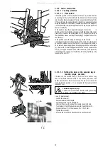
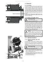
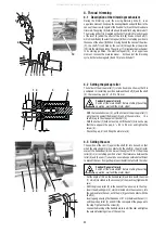
The retaining spring (1) holds the hook thread after having performed
the trimming. It is to be set in such a way that the force necessary for
pulling out the thread from the retaining spring (1) is approximately
equal to the force necessary for pulling out the thread from the hook.
Caution! Danger of injury!
Switch off the main switch! Before starting the setting
operation, wait until the motor stops!
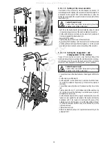
- Shape the retaining spring (1) in such a way that it fits close with all
its surface (without wedge) onto the moving trim-ming knife (3).
- Shape the retaining spring in such a way that it fits close, with the
slightly tightened screw (2), onto the moving trimming knife without
any pressure.
- Tighten the screw (2), until the necessary force for pulling the thread
from the retaining spring is attained. The pulling force is tested
using a screwdriver (4) according to the illustration.
Caution!
The setting of the retaining spring (1) depends on the
setting of the hook thread tension and differs then
according to the respective sewing category.
The adjusting screw (2) should not be screwed in in such a way
that the retaining spring gets over the perimeter of the moving
trimming knife.
4.9 Setting the switching of electromagnets
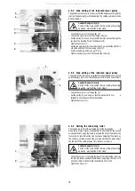
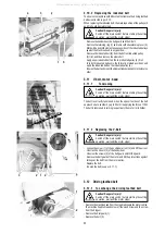
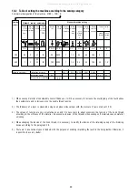
The electromagnets of the trimming device and loosening of the
tensioner must work in accordance with the diagram. This is ensured
by setting the stopmotor (see the instructions for use of the stopmotor).
1- 1. position of the needle (135
°
on the handwheel);
2- 2. position of the needle (64
°
on the handwheel)
3- position of stopping the tensioner (10
°
÷ 25
°
on the hand-wheel)
4- movement of the pickup roller
of the trimmer cam
5- current of the trimming device electromagnet
6- current of the tensioner loosening electromagnet
5
.
Lifting the top roller by electromagnet
5.1 Description
The core of the electromagnet, respectively its pin must be set in such
a way that the presser foot lifting is enabled.
5.2 Setting the electromagnet pin
Caution! Danger of injury!
Switch off the main switch! Before starting the setting
operation, wait until the motor stops!
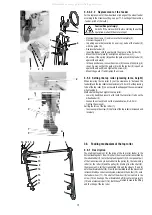
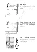
- Unscrew the cap of the core (1) of the electromagnet.
- Shift the core (2) with the pin (3) and unscrew the locking screw (4).
-
Unscrew the pin (3) in the core (2) in the A direction up to
the stop.
- Push the core (2) into the magnet (5) in the B direction
up to the stop.
- In this position, set the maximum top roller lifting in the B
direction.
- Screw on and tighten the arresting screw (4).
- Screw on the cap (1).
4
5
6
1
3
2
2
4
1
3
5
A
B
3
2
1
3
1
3
1
2
4
All manuals and user guides at all-guides.com

