5
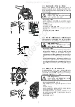
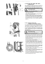
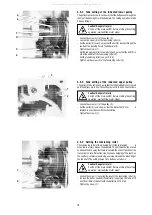
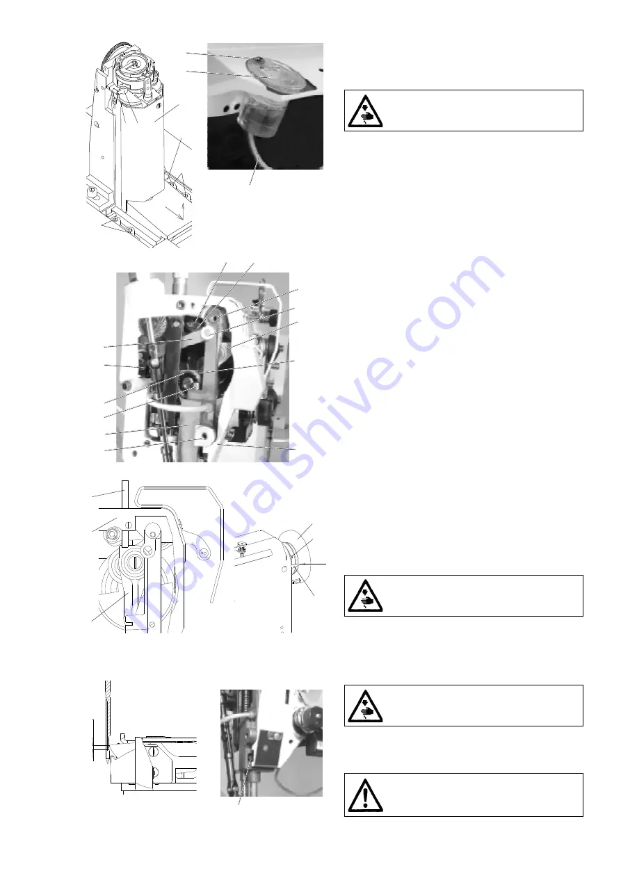
3.1.10 Dismantling of the hook post
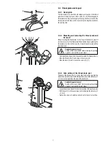
When dismantling the post (1), the supplies of lubricating oil are to be
disconnected first, the fastening screws unscrewed and, thereafter, the
post is removed.
Caution ! Danger of injury!
Switch off the main switch! Before starting the setting
operation, wait until the motor stops!
- Unscrew the screw (2).
- Push the lubricating tube (3) downwards into the post.
- Unscrew the screw (7) from the oil tank (8) and pull the tank out
from the machine.
- Disconnect the hose with the wick (9) from the oil tank (8).
- Loosen only one screw (5).
- Unscrew the screws (6).
- Shift the post in the sense of the arrows and remove it out from the
machine.
- When mounting it, proceed inversely.
3.2 Needle and thread mechanism
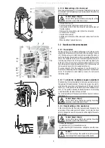
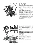
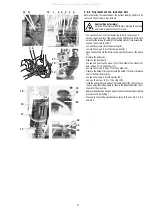
3.2.1 Description
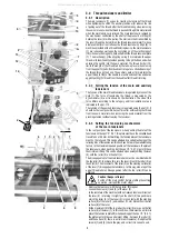
The take-up lever (1) is mounted in ball bearings, both at the spot of its
suspending on the connecting rod (2) and in the mounting on the loop
(12). The take-up lever is of aluminum and is provided with a stuck-in
eye for two threads. The connecting rod (2) is mounted on the eccentric
pin (3). The needle rod holder (4) is mounted through the pivot (5) in
a rotating way in the arm (6). In its top part, the holder is guided by the
guide pin (7). The movement for the needle feed is given to it by the
connecting rod (8) driven by the feeding shaft (9). The connecting rod
(8) is mounted by pin (13) with needle bar holder (4).
The connecting rod (10) of the needle bar (11) on the loop (12) is
mounted in a ball bearing and it is slidingly mounted on the needle bar
carrier. The mechanism is lubricated by means of a central-wick
lubricating system.
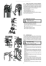
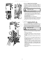
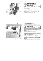
3.2.2 To check the handwheel angular adjustment
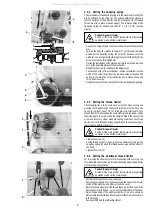
The handwheel (5) must be situated in its precise position relative to
the needle and thread mechanism. This position is given by a pin (2),
which locks the connecting rod of the needle rod (1) through a hole in
the arm (3). In this position, the indicator (6) of the handwheel must
show O. The position is fixed by the handwheel screw (4) contacting
a small flat surface provided on the upper shaft.
The correct adjustment of the angular position has been car-ried out at
the producers.
Caution ! Danger of injury!
Switch off the main switch! Before starting the setting
operation, wait until the motor stops!
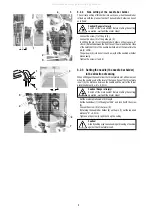
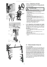
3.2.3 Height setting of the needle bar
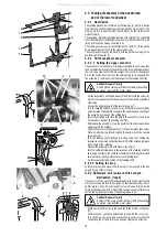
At the moment, when the hook point passes around the needle, the
upper edge of the needle eye must be about 1 mm below the hook
point. In an opposite case, it is necessary to set the height of the needle
bar as follows:
Caution ! Danger of injury!
Switch off the main switch! Before starting the setting
operation, wait until the motor stops!
- Remove the front guard.
- Loosen the screw (1) of the needle bar carrier
- Set the correct height of the needle bar and tighten anew the screw
(1).
Caution !
An incorrect setting of the needle bar height may cause
the striking of the hook point against the needle.
0
o
2
1
12
3
4
5
6
7
8
9
13
10
11
1
2
3
4
5
6
1
1
1
5
6
6
3
2
7
8
9
All manuals and user guides at all-guides.com


