background image

6.3

Checking ands adjusting the positions

There is no need to make any mechanical adjustments on the position
transmitter. It is only necessary to check the stop position and, if
required, to set the reference position before the first use of the
machine..

Position

0

1

2

Stop position

Position of the automatic sewing unit 

Reference position
Thread take-up lever short before its top dead
centre,
Rig pin 1 in the groove of the arm shaft 

Needle bottom position
( bottom dead centre )

Thread take-up lever short before the top dead
centre,
Rig pin 1 in the groove of the arm shaft 
( = Position 0 )

Thread take-up lever in its top dead centre,
The needle does not project under the sewing
basket. ( short after Position 2 )
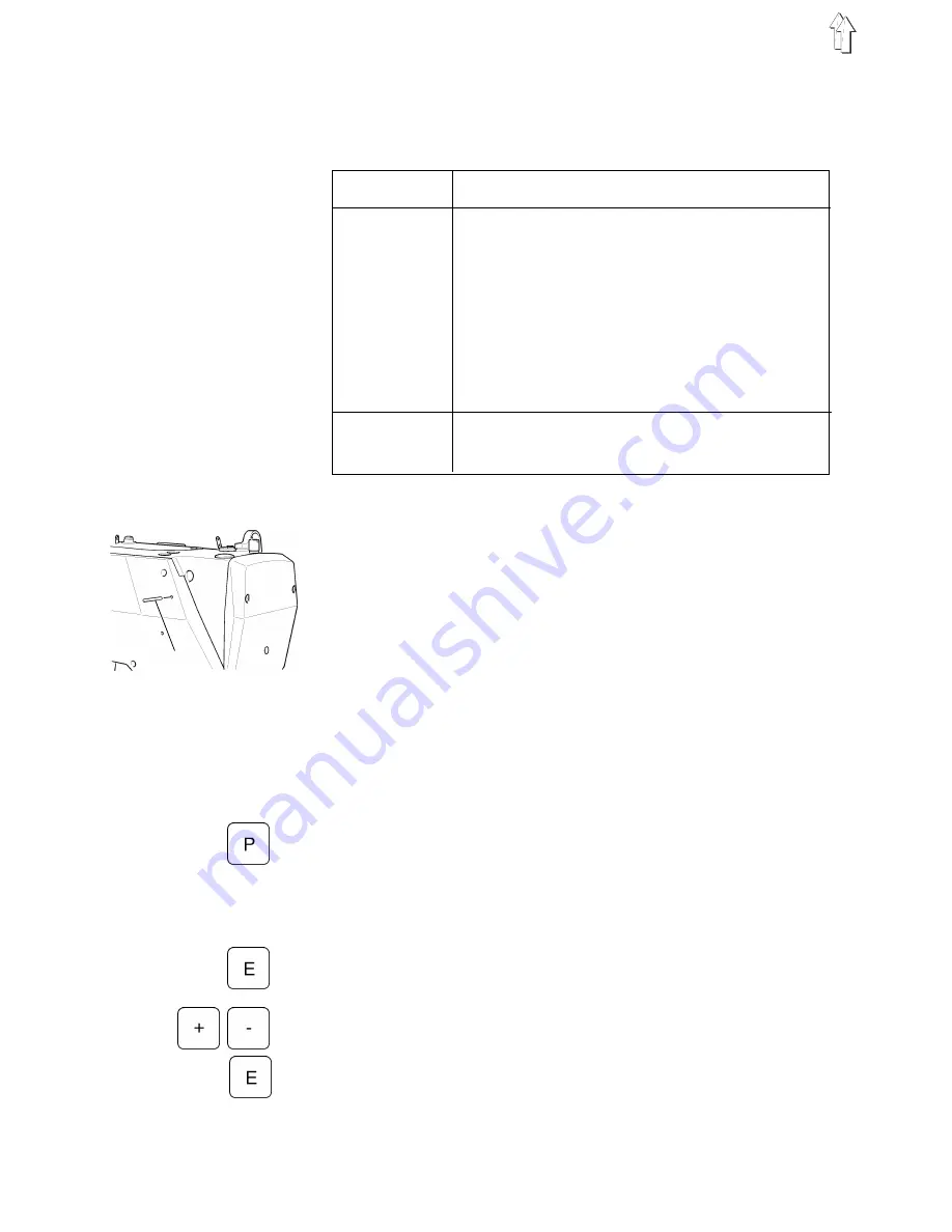
Check stop position

Connect main switch.
The machine runs into stop position or it is already in the stop
position, i.e.:

The thread take-up lever stands in the top dead centre.

The needle does not project under the sewing basket.

0 position can be reached by a slight rotation of the
handwheel against the arrow direction. The rig pin 1 will then
snap into the groove of the arm shaft..

Complete a full sewing sequence.
If the stop position is not reached, the display of the control panel
will present the error message "_0 0 1 0".
Then it will be necessary to set the reference position as follows:

Setting the reference position

Call up correction mode

Disconnect main switch.

Hold the key "P" on the control panel pressed down and connect
main switch.

Release the key "P".

Change over to the techician level

Enter Code-Number "1907".
( See Operating Instructions of the manufacturer. )

Press the key "E".
The control will change over to the technician,
the parameter "F -  100" will be displayed.

Enter reference position

Select parameter number "F -  170".

Press the key "E".
The display will show "Sr  1".

1

14

Summary of Contents for 577-1111

Page 1: ...p in position 9 5 2 Place machine head in position and connect 9 5 3 Adjusting the damping 9 5 4 Adjusting and connecting the pedal 10 5 5 Installing and connecting the control panel 11 5 6 Placing an...

Page 2: ...Fig A 10 4 6 13 14 1 5 12 7 8 9 11 2...

Page 3: ...witch 6 Sewing motor 7 Stand 8 Conditioning unit 9 Machine head 11 Drawer 12 Pedal rods 13 Pedal 14 Auxiliary equipment depending on the order e g sewing light 10 Tools and small parts in the accessor...

Page 4: ...vailable nuts and washers In case of not fully assembled automatic sewing units Fasten the main switch 2 under the table top Fasten the electrical connection cables under the table top 3 2 Setting the...

Page 5: ...1 2 3 5...

Page 6: ...be supplied for the automatic sewing unit cl 577 1111 Sewing motor Control panel Set point generator Belt pulley V belt Wiring diagram Fastening and connection material 4 2 Installing the sewing motor...

Page 7: ...y qualified electricians or by the properly qualified staff The mains plug must be pulled out It is absolutely necessary to respect the manufacturer s instructions supplied together with the sewing mo...

Page 8: ...er of the sewing motor If necessary change the connections according to the local voltage The direct current sewing drives are operated by a single phase a c current In order to avoid an overload of a...

Page 9: ...ox by two persons who should seize it at the shaft end and under the base plate but not in the area of the needle thread cutter Hang the machine head into the base 4 and turn in the screws 6 Clamp the...

Page 10: ...he pedal can be adapted to the different working positions as follows Lift the ball handle 3 Turn the pedal platform 4 according to the working position and let the ball handle 3 engage in the end pos...

Page 11: ...control panel 10 on the table top Lead the connecting cable of the control panel to the control box by passing it through the hole in the table top Introduce the plug of the control panel into the bus...

Page 12: ...d 1 Remove the V belt covering from the sewing drive Loosen the motor fastening nuts 4 and place the V belt 2 onto its pulley 5 on the sewing drive By swinging the entire sewing motor adjust the tensi...

Page 13: ...lip the position transmitter 6 onto the shaft Tighten the screws 7 Set the positions see chapter 6 3 6 2 Connecting the position transmitter Pass the connecting cable of the position transmitter throu...

Page 14: ...is already in the stop position i e The thread take up lever stands in the top dead centre The needle does not project under the sewing basket 0 position can be reached by a slight rotation of the han...

Page 15: ...Parameter F 170 if the reference position has not been memorisd and the display shows the error message in A3 Quit the correction mode Press the key P two times The sewing basket will be lifted Memor...

Page 16: ...nnect the conditioning unit by a connection hose 9 mm 3 to the compressed air line Pneumatic connection package Under the reference number 0797 003031 it is possible to obtain a pneumatic connection p...

Page 17: ...For filling the oil supply containers used exclusively the lubrication oil ESSO SP NK 10 or an equivalent oil with the following specification Viscosity at 40 C 10 mm2 s Point of inflammation 150 C Th...

Page 18: ...eable to slightly lubricate the wicks and the felt parts 8 3 Regulating the hook lubrication NOTE For ensuring a sufficient lubrication during the run in period a rather high oil supply quantity has b...

Page 19: ...F ACCIDENTS Switch off the main switch Switch off the machine before threading the needle and the hook Threading the needle and the hook see the Service Instructions Insert the material to be sewn Sta...

Reviews: