Page
Appendices
Dukane Manual Part No. 403-583-00
No.
Description
Page
2-I
iQ
Generator Weights ........................................................................................................9
3-I
Standard IEC AC Power Cord Part Numbers .................................................................17
3-II
Generator Input/Output Signals ......................................................................................18
6-I
Tip Torque Unit Conversions ...........................................................................................42
6-II
Stud Torque Unit Conversions ........................................................................................43
6-III
Horn/Booster Torque Unit Conversions ...........................................................................45
7-I
Pop-up Fault Status Screens ..........................................................................................53
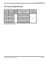
8-I
AC Power Requirements ................................................................................................59
List of Tables
Appendix B
Continued
5-15
Trigger Watts .................................................................................................................34
5-16
Trigger Timeout .............................................................................................................34
5-17
Setup Maintenance - 1 ..................................................................................................35
5-17A Pop-up Load Defaults? ..................................................................................................35
5-18
Setup Maintenance - 2 ..................................................................................................35
5-19
Setup Maintenance - 3 ..................................................................................................35
5-20
Set Time ........................................................................................................................36
5-21
New Setup Saved ..........................................................................................................36
5-22
Default Setup Screen ....................................................................................................36
6-1
Probe, Horn and Tip ......................................................................................................40
6-2
Probe, Booster and Horn ...............................................................................................41
6-3
Replaceable Tip Installation ..........................................................................................42
6-4
Stack Assembly Procedure ...........................................................................................44
6-5
Probe Assembly and Disassembly ................................................................................46
6-6
Separating the Horn from the Booster ...........................................................................47
6-7
Removing a Replaceable Tip From the Horn ................................................................47
8-1
Generator Outline Drawing ............................................................................................57
Appendix C
List of Figures


