background image

Section 8 –  Specifications

Page 41

Dukane Manual Part No. 403-608-00

PIC

TO

R

IA

L V

IE

W

:

SC

A

LE

 2 /

 3

PO

W

ER

 IN

LE

T

10

0-2

40

 V

AC

M

AX

IM

U

M

 (8

) P

R

O

BE

S

9.1

2

[2

32

]

.8

8

[2

2]

.8

5

[2

2]

O

PT

IO

N

AL


BO

TT

O

M


H

EA

T S

IN

K

AN

D

 M

O

U

N

TIN

G

FE

ET

9.2

5

[2

35

]

9.5

0

[2

41

]

AL

LO

W

 3

.0

0" 

[7

6] 

FO

R

 C

AB

LE

C

O

N

N

EC

TO

R

11

.2

5

[2

86

]

10

.7

3

[2

73

]

10

.6

1

[2

69

]

9.8

5

[2

50

]

7.3

8

[1

87

]

4.5

0

[1

14

]

.7

5

[1

9]

6.0

0

[1

52

]

.6

9

[1

8]

.8

9

[2

2]

2.0

0

[5

1]

LO

W

ER

M

O

U

N

TIN

G


BR

AC

KE

TS

11

.2

5

[2

86

]

D

IS

TA

N

C

E C

O

N

N

EC

TO

R

1.7

8

[4

5]

BO

TT

O

M

 R

EA

R

M

O

U

N

TIN

G

 B

R

AC

KE

T

10

.3

8

[2

64

]

9.5

0

[2

41

]

U

SB

 2

.0

ET

H

ER

N

ET

AN

YB

U

S C

O

N

N

EC

TIO

N

2.0

0

[5

1]

5.1

1

[1

30

]

4.1

5

[1

05

]

.7

2

[1

8]

1.7

8

[4

5]

TO

P R

EA

R

M

O

U

N

TIN

G

 B

R

AC

KE

T

BA

SE

 M

O

U

N

TIN

G

BR

AC

KE

TS

 (2

)

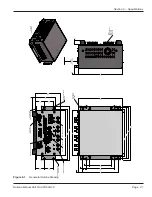
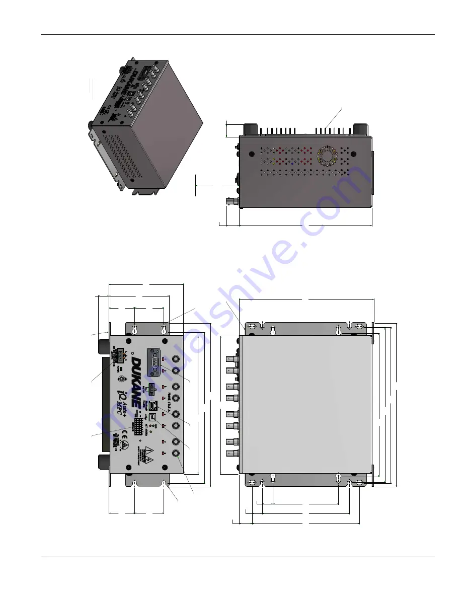
Figure 8-1


Generator Outline Drawing

Summary of Contents for Auto-Plus MPC iQ Series

Page 1: ...8 00 iQ Series ULTRASONIC GENERATOR POWER SUPPLY Auto Plus MPC User s Manual Dukane 2900 Dukane Drive St Charles Illinois 60174 USA TEL 630 797 4900 Dukane products are manufactured in ISO registered facilities AUTOMATED PRESS HAND PROBE ...

Page 2: ...in any form or by any means electronic mechanical photocopying recording or by any information storage and retrieval system without written permission from Dukane Notice of Liability The information contained in this manual is distributed on an As is basis without warranty While every precaution has been taken in the preparation of this manual Dukane shall not have any liability to any person or e...

Page 3: ...Page iii Dukane Manual Part No 403 608 00 Revision History Revision Revision Number Summary Date 00 Original release June 13 2019 ...

Page 4: ...Page iv iQ Series Auto Plus MPC User s Manual Dukane Manual Part No 403 608 00 This page intentionally left blank ...

Page 5: ...m Operational Test 22 LED Indication 24 Section 5 Options 27 Heat Sink 29 Distance Option 30 Section 6 Automation Interface 31 E Stop Wiring and Automation System Safety Circuit 33 iQLinQ 34 Section 7 Contacting Dukane 35 Section 8 Specifications 39 Generator Outline Drawing 41 Weight Operating Environment 42 AC Power Requirements 43 Interpreting the Model Number 44 Section 9 Appendices 47 Index 5...

Page 6: ...Page vi iQ Series Auto Plus MPC User s Manual Dukane Manual Part No 403 608 00 This page intentionally left blank ...

Page 7: ... Dukane Manual Part No 403 608 00 SECTION 1 Introduction General User Information 3 Read The Manual First 3 Notes Cautions and Warnings 3 Drawings and Tables 3 Generator Overview 4 Key Generator Features 4 Thermal Considerations 5 ...

Page 8: ...Page 2 iQ Series Auto Plus MPC User s Manual Dukane Manual Part No 403 608 00 This page intentionally left blank ...

Page 9: ...els of important information These statements help you to identify and avoid hazards and recognize the conse quences One of three different symbols also accompany the CAUTION and WARNING blocks to indicate whether the notice pertains to a condition or practice an electrical safety issue or a operator protection issue CAUTION Caution statements identify conditions or practicesthatcouldresult in dam...

Page 10: ...rn booster transducer and ad justs the generator output frequency to match it This is done for every weld cycle and eliminates the need to manually tune the generator Line Voltage Regulation automatically maintains constant amplitude regardless of line voltage devia tion The available output power is maintained with any voltage input within the specified range This provides consistent system perfo...

Page 11: ...t No 403 608 00 Thermal Considerations The thermal design of this generator is for applications that require 100 of rated power at no more than a 50 duty cycle NOTE Add transducer cooling as necessary to keep front mass temperature to 110 F or less ...

Page 12: ...Page 6 iQ Series Auto Plus MPC User s Manual Dukane Manual Part No 403 608 00 This page intentionally left blank ...

Page 13: ...Page 7 Section 2 Health and Safety Dukane Manual Part No 403 608 00 SECTION 2 Health and Safety General Considerations 9 Plastics Health Notice 10 Electrical Safety 10 Power Grounding Connection 11 ...

Page 14: ...Page 8 iQ Series Auto Plus MPC User s Manual Dukane Manual Part No 403 608 00 This page intentionally left blank ...

Page 15: ...astic assembly equipment is used with automatic material handling equipment in an automated system Foot Switch Do not use a foot switch Using a foot switch in place of the optical touch finger switches oper ate switches violates OSHA regulations Do not install a foot switch NOTE These recommendations apply to the welding system System in this manual refers to a complete group of components associa...

Page 16: ...ith Dukane ultrasonic equipment Electrical Safety The iQ Series generator provides the operating power and power returns Make sure the generator is grounded properly In addition to the safety considerations proper grounding is essential for the effective suppression of RFI Radio Frequency Interference Every generator contains a RFI filter which blocks noise on theAC power line from enter ing the g...

Page 17: ...electrical power source contact a qualified electrician Terminal Wire Color North America Europe L Live Black Lt Brown Ground Green Green w yellow stripe N Neutral White Lt Blue Table 2 I Conventional Wire Color Code L N iQ Auto Plus Power Inlet Pluggable AC Line Connector For safe system operation To avoid the risk of fire electri cal shock serious injury or death the power line safety ground mus...

Page 18: ...Page 12 iQ Series Auto Plus MPC User s Manual Dukane Manual Part No 403 608 00 This page intentionally left blank ...

Page 19: ...Page 13 Section 3 Installation Dukane Manual Part No 403 608 00 SECTION 3 Installation Unpacking 15 Placement 15 Power Grounding 16 Chassis Grounding Stud 16 Connecting Cables 17 Basic Connections 17 ...

Page 20: ...Page 14 iQ Series Auto Plus MPC User s Manual Dukane Manual Part No 403 608 00 This page intentionally left blank ...

Page 21: ...mount the unit vertically or horizontally in your equipment cabinet If the generator is installed inside an enclosure with a door be sure there is adequate clearance for the system cables with the door closed Placement in a Seismic Region If the iQ generator is to be used in an active seismic region secure the unit by rack mounting it or by securing the unit to a benchtop Refer to Dukane s website...

Page 22: ... operate effectively it is necessary to correctly ground the system The power line ground previously mentioned is manda tory Additionally the included grounding wire must be con nected from the grounding stud connection see Figure 3 1 to the nearest grounded metal pipe or equivalent earth ground This will improve the chassis ground connection and may be needed in noisy industrial environments See ...

Page 23: ...ing stud D in Figure 3 2 to earth ground 5 Connect the included E STOPterminal block to a switch or jumper the two connections together E in Figure 3 2 Plug the terminal block into the E Stop port Figure 3 2 Generator Front View NOTE AC Power Inlet Line voltage required for the generator is 100 240VAC at 50 60 Hz and 15 Amps Maximum The unit does not include a power switch and is powered ON whenev...

Page 24: ... fully shielded coaxial ultrasound cables that are secured with a simple and reliable quarter turn bayonet style attachment mechanism The ultrasonic output from this con nector that drives the attached ultrasonic load is a very high AC volt age 1200VAC At high power levels this can exceed 2 amps of current and must be securely terminated via the ultrasound cable for safe operation Use original equ...

Page 25: ...Page 19 Section 4 System Operation Dukane Manual Part No 403 608 00 SECTION 4 System Operation Introduction 21 iQ Auto Plus System Operational Test 22 LED Indication 24 ...

Page 26: ...Page 20 iQ Series Auto Plus MPC User s Manual Dukane Manual Part No 403 608 00 This page intentionally left blank ...

Page 27: ...eet the machine builder s requirements This unit is automation ready and has the capability of controlling up to 8 probes The generator s USB Ethernet and optional ANYBUS ports extend communication and control functions depending on the specifications of a particular generator model This section deals primarily with basic operational testing and troubleshooting ...

Page 28: ...rasound output by using iQLinQ or iQ Commander Normal Condition The system is operating properly when power is delivered to the attached stack 4 Check the operational Status LED Figure 4 1 Generator POWER LED Detail An Overload Fault latches until the next time U S is activated Any Fault status activates when any fault is de tected by the system It latches until the start of the next cycle unless ...

Page 29: ...es input selection bits Select a channel PROBE SELECTION STATUS indicator illuminates GREEN when it is the selected channel Activate ultrasound Activate the iQ Auto Plus ul trasound output The PROBE SELECTION STATUS indicator on the selected channel should switch to RED from GREEN The probe on the selected channel should deliver ultrasonic power Repeat this test for all MPC channels ...

Page 30: ...ED Indication There are seven LEDs on the iQ Auto Plus generator POWER 1 ETHERNET 2 MOD 1 NET 1 STATUS 1 PROBE SELECTION 2 4 6 or 8 Figure 4 2 shows LED location and Table 4 I shows their indications Figure 4 2 LED Locations POWER ETHERNET MOD STATUS NET PROBE SELECTION STATUS LED ...

Page 31: ... Steady Unrecoverable Fault Red Blinking Minor Fault Green Steady Device Operational Green Blinking Standby Gray Off No power NET Red Steady Duplicate IP Not Supported Red Blinking Connection Time Out Green Steady Connection Green Blinking No Connection STATUS Green Steady Ready Yellow Steady E STOP Active Orange Steady In Cycle Red Steady Average Overload Red Blinking Peak Overload Orange Blinkin...

Page 32: ...Page 26 iQ Series Auto Plus MPC User s Manual Dukane Manual Part No 403 608 00 This page intentionally left blank ...

Page 33: ...Page 27 Section 5 Options Dukane Manual Part No 403 608 00 SECTION 5 Options Heat Sink 29 Distance Option 30 ...

Page 34: ...Page 28 iQ Series Auto Plus MPC User s Manual Dukane Manual Part No 403 608 00 This page intentionally left blank ...

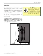
Page 35: ... package is 438 1020 The cooling package is standard on 1200 watt models and includes a heat sink that mounts to the generator as shown in Figure 5 1 below When operating an iQ Auto Plus MPC generator with the optional heat sink do so with the generator in the vertical position as shown in Figure 5 1 Air flow is enhanced and the heat sink s efficiency is maximized CAUTION Operate the iQ Auto Plus ...

Page 36: ... Manual Part No 403 608 00 Distance Option The weld by distance feature can monitor up to eight analog 0 10 VDC encoders A maximum of one customer supplied encoder for each MPC channel See https documents dukane com AppNote AN528 pdf for more information ...

Page 37: ...Section 6 Automation Interface Page 31 Dukane Manual Part No 403 608 00 SECTION 6 Automation Interface E STOP Switch Diagram 33 Automation System Safety Circuit 33 iQLinQ 34 TM ...

Page 38: ...Page 32 iQ Series Auto Plus MPC User s Manual Dukane Manual Part No 403 608 00 This page intentionally left blank ...

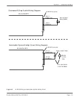
Page 39: ...ircuit iQ Auto Plus MPC Enable Out Enable In Dedicated E Stop Switch Wiring Diagram E STOP Connector Pin 1 Pin 2 User supplied E stop switch Enable Out Enable In Automation System Safety Circuit Wiring Diagram E STOP Connector Pin 1 Pin 2 User automation control hardware Master control relay Relay contact block iQ Auto Plus MPC ...

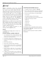
Page 40: ...eak Power Dis tance and or Position Set associated values in seconds joules watts or millimeters inches 2 SetAmplitude Ramp Up Time and Ramp Down Time 3 Enable and set Trigger by Power or Trigger By Position parameters 4 Enable and set Hold time 5 Enable and set Afterburst delay and duration 6 Enable checking for Suspect Parts Set maximum and minimum values for Time Power Energy Distance and or po...

Page 41: ...Section 7 Contacting Dukane Page 35 Dukane Manual Part No 403 608 00 SECTION 7 Contacting Dukane ...

Page 42: ...Page 36 iQ Series Auto Plus MPC User s Manual Dukane Manual Part No 403 608 00 This page intentionally left blank ...

Page 43: ...can be solved over the telephone so it is best to call from a telephone located near the equipment Mailing Address Dukane 2900 Dukane Drive St Charles IL 60174 USA Phone 630 797 4900 E mail ussales dukane com Fax Main 630 797 4949 Service Parts 630 584 0796 Website The website has information about our products processes solutions and technical data Downloads are available for many kinds of litera...

Page 44: ...Page 38 iQ Series Auto Plus MPC User s Manual Dukane Manual Part No 403 608 00 This page intentionally left blank ...

Page 45: ...ons Page 39 Dukane Manual Part No 403 608 00 SECTION 8 Specifications Generator Outline Drawing 41 Weight 42 Operating Environment 42 AC Power Requirements 43 Interpreting the Model Number 44 Regulatory Agency Compliance 45 ...

Page 46: ...Page 40 iQ Series Auto Plus MPC User s Manual Dukane Manual Part No 403 608 00 This page intentionally left blank ...

Page 47: ... 9 50 241 ALLOW 3 00 76 FOR CABLE CONNECTOR 11 25 286 10 73 273 10 61 269 9 85 250 7 38 187 4 50 114 75 19 6 00 152 69 18 89 22 2 00 51 LOWER MOUNTING BRACKETS 11 25 286 DISTANCE CONNECTOR 1 78 45 BOTTOM REAR MOUNTING BRACKET 10 38 264 9 50 241 USB 2 0 ETHERNET ANYBUS CONNECTION 2 00 51 5 11 130 4 15 105 72 18 1 78 45 TOP REAR MOUNTING BRACKET BASE MOUNTING BRACKETS 2 Figure 8 1 Generator Outline ...

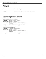
Page 48: ...nt dry Minimize exposure to moisture dust dirt smoke and mold Humidity 5 to 95 non condensing 5 C to 30 C Nonoperating storage guidelines Temperature 4 F to 158 F 20 C to 70 C Air Particulates Keep the equipment dry Minimize exposure to moisture dust dirt smoke and mold Humidity 5 to 95 non condensing 0 C to 30 C Weight Standard Model 16 pounds 7 26 kg Shipping Add 5 pounds 2 3 kg to unit weight f...

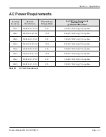
Page 49: ...20kHz 20AM060 UF CX XX 600 100 240V 50 60 Hz 15 Amps Max 20kHz 20AM120 2F CX XX 1200 200 240V 50 60 Hz 15 Amps Max 30kHz 30AM060 UF CX XX 600 100 240V 50 60 Hz 15 Amps Max 30kHz 30AM120 2F CX XX 1200 200 240V 50 60 Hz 15 Amps Max 35kHz 35AM060 UF CX XX 600 100 240V 50 60 Hz 15 Amps Max 35kHz 35AM120 2F CX XX 1200 200 240V 50 60 Hz 15 Amps Max 40kHz 40AM060 UF CX XX 600 100 240V 50 60 Hz 15 Amps Ma...

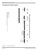
Page 50: ...iQLinQ Ethernet IP Interface C3 iQLinQ PROFINET Interface Module C4 iQLinQ CC Link Interface Module C5 iQLinQ POWERLINK Interface Module C6 iQLinQ EtherCAT Interface Module C7 iQLinQ Modbus TCP Interface Example System Number shown above 30AM120 2F C5 02 System Assembly Detailed Description 30kHz 1 200 Watt System operates on a 200 240V AC Line with a POWERLINK communications module and two point ...

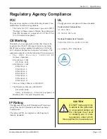
Page 51: ... Industrial EN 61000 6 4 2001 EN 55011 2003 EN 61000 6 2 2005 EN61000 4 2 EN61000 4 3 EN61000 4 4 EN61000 4 5 EN61000 4 6 EN61000 4 8 EN61000 4 11 The Low Voltage Directive 2006 95 EC The Machinery Directive 2006 42 EC EN 60204 2006 Safety of Machinery Electrical Equipment of Machines Part 1 General Requirements IP Rating The iQ generator has an IP International Protection rating from the IEC Inte...

Page 52: ...Page 46 iQ Series Auto Plus MPC User s Manual Dukane Manual Part No 403 608 00 This page intentionally left blank ...

Page 53: ...Section 9 Appendices Page 47 Dukane Manual Part No 403 608 00 SECTION 9 Appendices Appendix A List of Figures 49 Appendix B List of Tables 50 ...

Page 54: ...Page 48 iQ Series Auto Plus MPC User s Manual Dukane Manual Part No 403 608 00 This page intentionally left blank ...

Page 55: ... 2 1 AC Line Connection 11 3 1 Generator Mounting Bracket 15 3 2 Generator Front View 17 4 1 Generator POWER LED Detail 22 4 2 LED Locations 24 5 1 Generator with Heat Sink Option 29 6 1 E STOP Wiring and Automation System Safety Circuit 33 8 1 Generator Outline Drawing 41 8 2 Interpreting the Model Number 44 ...

Page 56: ... Series Auto Plus MPC User s Manual Dukane Manual Part No 403 608 00 Appendix B List of Tables No Description Page 2 I Conventional Wire Color Code 11 4 I LED Colors and Indication 25 8 I AC Power Requirements 43 ...

Page 57: ...Index Page 51 Dukane Manual Part No 403 608 00 Index ...

Page 58: ...Page 52 iQ Series Auto Plus MPC User s Manual Dukane Manual Part No 403 608 00 This page intentionally left blank ...

Page 59: ...l Safety Power Grounding Connection 11 F FCC 45 G General User Information 3 Drawings and Tables 3 Notes Cautions and Warnings 3 Read This Manual First 3 Generator Features 4 Overview 4 Thermal Considerations 5 H Health and Safety Electrical Safety 10 General Considerations 9 Plastics Health Notice 10 Recommendations 9 Heat Sink 29 I Installation Connecting Cables 17 Placement 15 Placement in a Se...

Page 60: ...istance Option 30 Heat Sink 29 R Regulatory Agency Compliance 45 S Specifications AC Power Requirements 43 Interpreting the Model Number 44 Operating Environment 42 Weight 42 System Operation Introduction 21 iQ Auto Plus System Operational Test 22 LED Indication 24 T Thermal Considerations 5 ...

Page 61: ...a minimum re quirement for these requirements and starts transitioning the company from a traditional inspection oriented quality system to one based on partnership for continuous improve ment This concept is key in that Dukane no longer focuses on inspection but on indi vidual processes Dukane s quality management system is based on the following three objectives 1 Customer oriented quality The a...

Page 62: ... Illinois 60174 USA TEL 630 797 4900 iQ Series Ultrasonic Generator Power Supply Auto Plus MPC User s Manual Printed in the United States of America www dukane com Please refer to our website at www dukane com contact us to locate your local representative ...

Reviews: