background image

Page  1

Page  0 

iQ Series

Ultrasonic Generator/Power Supply LS User’s Manual

Section 4 – Standard Connections

Dukane Manual Part No. 403-574-01

SECTION 4

Standard Connections

Rear Panel Layout Overview . . . . . . . . . . . . . . . . . . . . . . . . 23

AC Power Inlet Panel . . . . . . . . . . . . . . . . . . . . . . . . . . . . . . 24

IEC AC Power Inlet Connector . . . . . . . . . . . . . . . . . . . . . . . . . . . . . 24

Power Switch/Circuit Breaker . . . . . . . . . . . . . . . . . . . . . . . . . . . . . . 24

Chassis Grounding Stud . . . . . . . . . . . . . . . . . . . . . . . . . . . . . . . . . . 24

System I/O Panel . . . . . . . . . . . . . . . . . . . . . . . . . . . . . . . . . 24
S

ystem Inputs Connector  . . . . . . . . . . . . . . . . . . . . . . . . . . . . . . . . . . . 24

System Inputs Connector Pinout. . . . . . . . . . . . . . . . . . . . . . . . . . . . 25

System Inputs Signal Descriptions . . . . . . . . . . . . . . . . . . . . . . . . . . 26

System Outputs Connector. . . . . . . . . . . . . . . . . . . . . . . . . . . . . . . . 28

System Outputs Connector Pinout . . . . . . . . . . . . . . . . . . . . . . . . . . 28

System Outputs Signal Descriptions. . . . . . . . . . . . . . . . . . . . . . . . . 28

Ultrasound Output Connector . . . . . . . . . . . . . . . . . . . . . . . . . . . . . . 32

Configuration Port Connector 

. . . . . . . . . . . . . . . . . . . . . . . . . . . . . . 33

Summary of Contents for iQ LS

Page 1: ...lligent Assembly Solutions www dukane com us Dukane Part No 403 574 01 Series ULTRASONIC GENERATOR POWER SUPPLY LS User s Manual Dukane Intelligent Assembly Solutions 2900 Dukane Drive St Charles Illinois 60174 USA TEL 630 797 4900 FAX 630 797 4949 AUTOMATED HAND PROBE PRESS ...

Page 2: ...in the preparation of this manual the manufacturer shall not have any liability to any person or entity with respect to any liability loss or damage caused or alleged to be caused directly or indirectly by the instructions contained in this manual or by the hardware products described herein Printed in the United States of America Part Number 403 574 01 This ultrasonic equipment is manufactured un...

Page 3: ...wer models 09 21 2010 Update system I O pin descriptions Add Trigger by Power Add iQ LinQTM Web address revised Revise Regulatory Agency Compliance statement Health and Safety Add safe lifting practices Installation Add lockout tagout information and seismic zone information Page 25 Edited to clarify need for external power supply 11 24 2010 ...

Page 4: ...Page iv Dukane Manual Part No 403 574 01 This page intentionally left blank ...

Page 5: ...fety Lifting the Equipment Section 3 Installation 11 Before Installation Unpacking Placement RFI Grounding Connecting Cables Manually Operated Probe System Power Cords Automation Controlled Probe System Section 4 Standard Connections 21 Rear Panel Layout Overview AC Power Inlet Panel System I O Panel Section 5 Standard System Status and Controls 35 Front Panel Overview System Displays Control Keys...

Page 6: ...ooting 61 No Ultrasonic Output System Power Output Level Red System Power Diagnostics Procedures Welding Problems Pop up Status Screens Section 9 Maintenance 67 Section 10 Options 71 Power Inlet Options Electrical Safety AC Power Inlet Panel I O Panel Options Multi Probe Control MPC Interface Module Remote Amplitude Control Module Automation Thruster Control Module Isolated I O Conversion Module T...

Page 7: ...Introduction Dukane Manual Part No 403 574 01 SECTION 1 Introduction General User Information 3 Read the Manual First 3 Notes Cautions and Warnings 3 Drawings and Tables 3 Generator Overview 4 Key Generator Features 4 ...

Page 8: ...Page iQ Series Ultrasonic Generator Power Supply LS User s Manual Dukane Manual Part No 403 574 01 This page intentionally left blank ...

Page 9: ... to identify and avoid hazards and recognize the consequences One of three different symbols also accompany the CAU TION and WARNING blocks to indicate whether the notice pertains to a condition or practice an electrical safety issue or an operator protection issue Drawings and Tables The figures and tables are identified by the section num ber followed by a sequence number The sequence num ber be...

Page 10: ...nually tune the generator Line Voltage Regulation automatically maintains constant amplitude regardless of line voltage devia tion The available output power is maintained with any voltage input within the specified range This pro vides consistent system performance regardless of line voltage fluctuations It also eliminates the need for bulky external constant voltage transform ers Load Regulation...

Page 11: ...h Safety Dukane Manual Part No 403 574 01 SECTION 2 Health and Safety General Considerations 7 Plastics Health Notice 7 Electrical Safety 8 Domestic Power Grounding 8 International Power Grounding 8 Lifting the Equipment 9 ...

Page 12: ...Page iQ Series Ultrasonic Generator Power Supply LS User s Manual Dukane Manual Part No 403 574 01 This page intentionally left blank ...

Page 13: ...ver unless specifically directed to do so by the manu facturer The generator produces hazardous electrical voltages which could cause injury Grounded Electrical Power Operate this equipment only with a properly grounded electrical connection See Electrical Safety Grounding Instructions on the next page Comply with Regulations You may be required to add accessories to bring the system into complian...

Page 14: ...a properly grounded three prong type Have a qualified electrician replace it following the National Electric Code and any local codes and ordinances that apply See Figures 2 1 and 2 2 NOTE See Section 10 Options if your sys tem has a non detachable power cord for 120VAC operation Electrical Safety Domestic Power Grounding For safety the power cords used on this product have a three wire grounding ...

Page 15: ...feet not your torso To place the object below the level of your waist follow the same procedures in re verse order Remember keep your back as vertical as possible and bend at the knees Lifting the Equipment CAUTION Ta ke c a r e i n l i f t i n g t h e e q u i p m e n t W e recommend using a me chanical lift device to assist How to Lift Safely Before lifting take a moment to think about what you r...

Page 16: ...Page 10 iQ Series Ultrasonic Generator Power Supply LS User s Manual Dukane Manual Part No 403 574 01 This page intentionally left blank ...

Page 17: ...t No 403 574 01 SECTION 3 Installation Before Installation 13 When to Use Lockout Tagout Devices 13 Unpacking 15 Placement 15 RFI Grounding 18 Connecting Cables 19 Manually Operated Probe System 19 Power Cords 19 Automation Controlled Probe System 20 ...

Page 18: ...Page 12 iQ Series Ultrasonic Generator Power Supply LS User s Manual Dukane Manual Part No 403 574 01 This page intentionally left blank ...

Page 19: ...ice with lockout capability The LOTO device is placed over the plug end of the generator electrical cord This effectively prevents access to the energy isolation point See the example of one such device in the figure above The figure to the right shows the lockout device in the closed locked position Continued Figure 3 1 Lockout Device In Open Position Unlocked Figure 3 2 Bottom Lockout Device In ...

Page 20: ... Secure the shell with its lock and lock it 4 Wait a minimum of five minutes for the generator to discharge its electrical energy 5 After taking these steps make the necessary adjustments to the generator Assuming the generator is being put back into service Procedure to use AFTER making any internal adjustments to the generator 1 Authorized personnel remove the lockout tagout device from the plug...

Page 21: ...w a 3 inch space 8 cm at the rear of the chassis for cable clear ance See Specifications Section 11 for detailed generator drawings CAUTION Allow 5 inches for air venti lation at the cooling air inlet and at the exhaust air outlet The fan draws in fresh air to cool the internal compo nents reduce thermal gradients and increase component life Figure 3 3 Generator Front View low profile model 80 60 ...

Page 22: ...ile unit below Mount the generator to a 19 inch equipment rack Figure 3 4 Rack Mounting iQ Generator System Type Dukane Part Number High Profile 147 4721 Low Profile 147 4720 Table 3 I Rack Mount Bracket Part Numbers 400 2251 01 3 82 97 0 3 44 87 3 3 25 82 5 12 57 319 2 12 99 330 0 ALLOW 5 BOTH SIDES FOR COOLING ALLOW 5 BOTH SIDES FOR COOLING ALLOW 3 IN BACK FOR CABLES IN mm 25 X 50 SLOT 2 PLCS 18...

Page 23: ...e of each l bracket to the bench itself Figure 3 5 Securing iQ Generator to Benchtop 12 54 318 61 280 HOLE 18 04 458 15 18 84 478 47 OPTIONAL HOLD DOWN BRACKETS OPTIONAL HOLD DOWN BRACKETS 147 1398 ALLOW 5 BOTH SIDES FOR COOLING 400 2254 E IN mm ALLOW 3 IN BACK FOR CABLING 5 50 139 59 ALLOW 5 BOTH SIDES FOR COOLING 5 19 131 83 17 16 435 76 13 20 335 37 1 40 35 7 1 14 29 0 10 00 254 0 NOTE The figu...

Page 24: ...eing fed back into the AC power line In order for the RFI filter to operate properly it is necessary to cor rectly ground the system Run a grounding wire from the grounding stud connection to the nearest grounded met al pipe or equivalent earth ground and secure it with a ground clamp See Figure 3 6 on Page 20 CAUTION To minimize electri cal noise and eliminate ground currents ground the chassis a...

Page 25: ... Probe System Hand Probe Step 1 Ground the generator chassis using the supplied 14 Gauge wire and attach it to the grounding stud A in Figure 3 6 Step 2 Attach the hand probe s HD 15 system input con nector to J2 on the I O panel B in Figure 3 6 Step 3 Attach high voltage coaxial cable to J1 the ultra sound output connector C in Figure 3 6 Step 4 Connect the AC power cord to the IEC power inlet co...

Page 26: ...ip ment to the system input HD 15 connector J2 on the I O panel B in Figure 3 6 Step 4 Output Cable Attach an output cable DB25 type from J3 to your equipment to monitor sys tem status Step 5 Attach the high voltage coaxial cable from the probe to the ultrasound output connector J1 C in Figure 3 6 Step 6 Connect the AC power cord to the generator IEC power inlet connector and plug the other end in...

Page 27: ... Power Inlet Connector 24 Power Switch Circuit Breaker 24 Chassis Grounding Stud 24 System I O Panel 24 System Inputs Connector 24 System Inputs Connector Pinout 25 System Inputs Signal Descriptions 26 System Outputs Connector 28 System Outputs Connector Pinout 28 System Outputs Signal Descriptions 28 Ultrasound Output Connector 32 Configuration Port Connector 33 ...

Page 28: ...ge 22 iQ Series Ultrasonic Generator Power Supply LS User s Manual Dukane Manual Part No 403 574 01 Page 22 iQ Series Ultrasonic Generator Power Supply LS User s Manual This page intentionally left blank ...

Page 29: ... switch system power ON and OFF C Chassis Grounding Stud Chassis connection for a protective earth ground The System I O Panel D System Input Connector Connections for system control input signals E System Output Connector Connections for system status output signals F Ultrasound Output Connector Coaxial high voltage connection to ultrasonic stack G Configuration Port Connector Digital control por...

Page 30: ...rip is due to a transient condition the circuit breaker can be reset by switching the actuator back to the ON position If when resetting the circuit breaker after it has tripped it imme diately trips again there is likely an internal system mal function and the generator will require service Do not repeatedly try to reset the circuit breaker If it trips this will only cause more damage to the gene...

Page 31: ...tailed descriptions that follow The wire color coding for the system input cable is listed in Table 4 I to assist with custom automation system wiring and assembly NOTE Refer to Section 10 Options for information on optional features Figure 4 3 System I O Panel standard panel shown Note that a simple switch closure relay contact connect ed to a control input can not activate the input unless an ex...

Page 32: ...system This input is also used to select different channels when a Multiple Probe Controller MPC Interface option board is in stalled Pin Signal Name Cable Color Code Signal Option Requirements 1 22V BLK 2 Power Ground WHT 3 Remote Setup Selection Bit 0 Input RED MPC Option Required 4 Remote Setup Selection Bit 1 Input GRN MPC Option Required 5 Remote Setup Selection Bit 2 Input ORN MPC Option Req...

Page 33: ...ng process when the user wants to retract the ultrasonic stack away from the process or material when the ultrasound is off or some changes in the process are being made Pin 10 Front Panel Control Lock Input Pin 10 is used to lock the front panel user interface so an operator cannot change any welding setups or configuration parameters that are stored in memory The user can use the interface contr...

Page 34: ... The module converts the standard isolated sinking NPN status output signals to isolated sourcing PNP status output signals Consult your local sales representative for information about the conversion module System Outputs Connector Pinout The SYSTEM OUTPUTS connector is a DB 25F standard D subminiature 25 circuit female connector Connector pin assignments for this connector are shown in Figure 4 ...

Page 35: ...NOT AVAILABLE Pin 12 Current Loop OK Status Output This status output signal will activate only when a Remote Amplitude Control Board is installed in the system Pin 12 is a digital active low status output that activates when the current loop input to the remote control option board is connected and working normally This output will be an open circuit when the current loop input signal is too low ...

Page 36: ...atus output signal will also be open MPC NOT READY if a fault condition is detected inside the MPC system If this status output will not activate check for a red fault status indication the SYSTEM STATUS LED on the front of the MPC module Pin 19 System Power OK Status Output Pin 19 is a digital active low status output that activates when no fault conditions are detected by any of the power fault ...

Page 37: ...nal Option Requirements 1 22V BLK 2 Spare Output WHT 3 22V Power Ground RED 4 Programmable Status Output 1 GRN 5 Programmable Status Output 2 ORN 6 Ultrasound Active Status Output BLU 7 Any Fault Status Output WHT BLK 8 Press Trigger Status Output RED BLK Not Available 9 System Overload Status Output GRN BLK 10 System Online Status Output ORN BLK 11 Press Top of Stroke Status Output BLU BLK Not Av...

Page 38: ...with a simple and reliable quarter turn bayonet style attachment mechanism Figure 4 8 Ultrasound Output Connector CAUTION The ultrasonic output from this connector that drives the attached ultrasonic load is a very high AC voltage At high power levels this can exceed 2 amperes of current and must be securely terminated via the ultrasound cable for safe operation Use original equip ment ultrasound ...

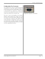
Page 39: ...CE on a computer via a standard 9 pin serial cable If the computer does not have a serial port you may use a USB to serial conversion cable This port is used for field updates to the generator firmware without removing the enclosure cover This port can also be used with a software application running on a Windows PC to modify the factory default system settings and hardware configurations Contact ...

Page 40: ...Page 34 iQ Series Ultrasonic Generator Power Supply LS User s Manual Dukane Manual Part No 403 574 01 This page intentionally left blank ...

Page 41: ...s Front Panel Overview 37 System Displays 37 System Power Output Level Bar Graph 37 System Operating Mode 37 4 line LCD Display 37 Control Keys 38 INFO 38 ON OFF Line 38 TEST 39 Arrow Keys 39 ENTER 39 CANCEL 39 Start up Sequence 40 Stopping the Weld Cycle 41 System Parameter Settings Overview 42 Default System Parameter Settings 42 ...

Page 42: ...Page 36 iQ Series Ultrasonic Generator Power Supply LS User s Manual Dukane Manual Part No 403 574 01 This page intentionally left blank ...

Page 43: ...esponding to the peak level remains on for about one second after the weld cycle has been completed Flash on Overload at 90 The OVERLOAD indicator begins to flash RED when the generator produces 90 of the overload power rating This feature alerts the operator to an impending overload fault condition Bar Graph Power Scaling Power scaling is related to amplitude At 100 amplitude the whole graph is l...

Page 44: ...OVER 40 0 20 SYSTEM POWER OUTPUT LEVEL SYSTEM OPERATING MODE ON LINE OFF LINE POWER TEST 1 PART COUNT 125 WELD TIME 0 080 S POWER 1050 W ENERGY 350 J I NFO O N OFF L I N E T E ST C A NCEL ENTE R Figure 5 2 Front Panel Control Detail Navigation Keys 4 WELD ENERGY HOTKEY AMPLITUDE PROCESS SETUP SYSTEM INFO Weld Method Time Energy Power programmed by the user Time is the default method Screen shown i...

Page 45: ...y s cursor left or right respectively Also use these keys to move up one level in the menu or to move back one level Press the up and down arrow keys to change the value of a selected digit ENTER Press the ENTER key to select a menu item shown by the selection indicators and move to the next level of the menu Think of it as a forward key Press ENTER to confirm and store a selection in memory CANCE...

Page 46: ...stem detail See the Start up 1 and 2 Figures 5 3 and 5 4 to the right 6 When the diagnostics sequence is finished the next screen to appear will look like Figure 5 5 This is the Process Data screen and that is linked to the OPERATE MODE menu This screen is updated after each weld cycle 7 Press CANCEL twice and you will be at the Main Menu as shown at right LOAD 80 60 100 OVER 40 0 20 SYSTEM POWER ...

Page 47: ...System Press OFFLINE to stop the ultrasound signal This may be done under any condition Automated System Customer supplied external controls provide the means to stop the cycle for an automated system An auxiliary cable connects these external controls to the iQ generator at connector J2 Control input labeled Automation Cycle Stop Input Pin 15 when activated will stop the weld cycle if configured ...

Page 48: ...rameter Settings Default Frequency Dependent Settings Setting Description 15kHz 20kHz 30kHz 40kHz Free Running Frequency Setting Hz 15 000 19 900 30 000 40 000 Upper Frequency Limit Setting Hz 15 400 20 400 30 500 40 500 Lower Frequency Limit Setting Hz 14 600 19 400 29 500 39 500 Ramp up Time Setting sec 0 250 0 150 0 100 0 050 Phase Delay Setting degrees 0 0 0 0 Default Frequency Independent Set...

Page 49: ... Run Frequency minus 500 Hz Default Free Run Frequency plus 500 Hz Ramp up Time 0 010 second 1 250 second Phase Delay Default Phase Delay minus 20º Default Phase Delay plus 20º Table 5 III System Parameter Adjustment Limits NOTE Free Run Frequency for 15kHz generators Minimum Default Free Run Frequency minus 600 Hz Maximum Default Free Run Frequency plus 600 Hz System Parameter Adjustment Limits C...

Page 50: ...Page 44 iQ Series Ultrasonic Generator Power Supply LS User s Manual Dukane Manual Part No 403 574 01 This page intentionally left blank ...

Page 51: ... 403 574 01 Section 6 Process Control Settings User Provided Process Control Overview 47 Manual Welding 47 Automated Welding 47 Automated Process Control Input Signals 47 Status Output Signals 47 Screen Navigation Basics 48 Programming the Generator Some Examples 49 ...

Page 52: ...Page 46 iQ Series Ultrasonic Generator Power Supply LS User s Manual Dukane Manual Part No 403 574 01 This page intentionally left blank ...

Page 53: ...front panel process controller controls the welding process Output signals from the PLC system will determine when the ultrasound or weld cycle starts Control signals for a Multiple Probe Control MPC system can also be easily added if needed A variety of ultrasonic welding status output signals are available to the automation system which are useful in monitoring the welding process Automated Proc...

Page 54: ... Press ENTER The screen you see is the one that ap pears just after the generator is first switched ON 4 After viewing this screen press CANCEL once to return to the OPERATE MODE menu 5 Press the down arrow key and select PROCESS STATISTICS 6 Press ENTER The next screen shows part statistics 7 Press CANCEL to return to OPERATE MODE selections 8 Using the up and down arrow keys select SYSTEM PARAME...

Page 55: ...TUP HARDWARE SETUP PROCESS SETUP PROCESS CONTROL PROCESS LIMITS UTILITIES AUTOMATED PROBE WELD CONTROL BY iQ SYSTEM AUTOMATION HOW TO Have a PLC Control the Ultrasound Activation Programming the Generator Some Examples On the following pages these programming examples cover how to Have a PLC Control the Ultrasound Activation Weld by Time Weld by Energy Adjust Amplitude Adjust Ramp Up Time Soft Sta...

Page 56: ...WN arrows to select the value time in seconds of each digit 8 When done with the time entry press ENTER and an ENTRY ACCEPTED message will appear 1 OPERATE MODE PROCESS SETUP HARDWARE SETUP PROCESS SETUP PROCESS CONTROL PROCESS LIMITS UTILITIES AUTOMATED PROBE WELD CONTROL BY iQ SYSTEM AUTOMATION WELD CONTROL HOLD CONTROL AFTERBURST CONTROL AMPLITUDE CONTROL WELD BY TIME WELD BY PEAK POWER WELD BY...

Page 57: ...lue energy in Joules 8 When done with the energy entry press ENTER and an ENTRY ACCEPTED message will appear 1 OPERATE MODE PROCESS SETUP HARDWARE SETUP PROCESS SETUP PROCESS CONTROL PROCESS LIMITS UTILITIES AUTOMATED PROBE WELD CONTROL BY iQ SYSTEM AUTOMATION WELD CONTROL HOLD CONTROL AFTERBURST CONTROL AMPLITUDE CONTROL WELD TIME 0 000 S SELECT DIGIT SELECT VALUE WELD BY TIME WELD BY PEAK POWER ...

Page 58: ...is is a value with a minimum of 20 and a maximum of 100 Select the digits with the RIGHT and LEFT arrows Use the UP and DOWN arrows to select the value 8 When done with the amplitude entry press ENTER and an ENTRY ACCEPTED message will appear 1 OPERATE MODE PROCESS SETUP HARDWARE SETUP PROCESS SETUP PROCESS CONTROL PROCESS LIMITS UTILITIES AUTOMATED PROBE WELD CONTROL BY iQ SYSTEM AUTOMATION WELD ...

Page 59: ...s maximum operating amplitude smoothly reducing shock stress 1 As in the previous HOW TO example navigate to the AMPLITUDE CONTROL screen 2 Select RAMP UP DOWN TIME and then press ENTER 3 A WARNING will appear as shown to the right Call Dukane Service with any questions about mak ing this adjustment 4 Select the feature Ramp Up Time or Ramp Down Time you want to adjust Adjust ramp up down times Se...

Page 60: ...Page 54 iQ Series Ultrasonic Generator Power Supply LS User s Manual Dukane Manual Part No 403 574 01 This page intentionally left blank ...

Page 61: ...nual Part No 403 574 01 SECTION 7 System Operational Testing System Verification Tests 57 Preliminary Setup 57 Testing the Generator 57 System Test 58 Probe Operation 59 Stopping the Ultrasound Output 59 System with a User supplied Emergency Stop Switch 59 ...

Page 62: ...Page 56 iQ Series Ultrasonic Generator Power Supply LS User s Manual Dukane Manual Part No 403 574 01 This page intentionally left blank ...

Page 63: ...LINE The System Operating Mode ONLINE indicator G will be green d Press the TEST key E Ultrasound should activate and the first segment of the SYSTEM POWER OUTPUT LEVEL bar graph turns green H Release theTEST switch Ultrasound should deactivate and the SYSTEM POWER OUTPUT LEVEL bar graph should be OFF gray Step 6 Optionally system status outputs can be moni tored during this test The ultrasound st...

Page 64: ...ormal There should not be any loud or unusual noise Step 4 Momentarily press the TEST control key E in Figure 7 5 Step 5 The first segment LED of the SYSTEM POWER OUTPUT LEVEL bar graph H in Figure 7 5 turns green The probe will operate as long as the TEST key is pressed Step 6 When the TEST key is released the SYSTEM POWER OUTPUT LEVEL bar graph turns off gray This test cannot be performed with t...

Page 65: ...rgy will be processed and then the ultrasound will be shut off Automation System The programmed weld time will be processed and then the ultrasound will shut off NOTE Neither a hand probe or an automa tion system can trigger the generator to produce an ultrasound output if the generator is OFFLINE Stopping the Ultrasound Output Set mode key C to OFFLINE Ultrasound will deactivate Figure 7 6 Stop U...

Page 66: ...Page 60 iQ Series Ultrasonic Generator Power Supply LS User s Manual Dukane Manual Part No 403 574 01 This page intentionally left blank ...

Page 67: ...tor 63 Operate Input 63 System Power Output Level Red 64 Red Fault Condition 64 Overload 64 Over Temperature 64 Generator Fault Does Not Reset 64 System Power Diagnostic Procedures 64 AC Line Fault 64 DC Bus Fault 64 Control Power Supply Fault 64 Welding Problems 65 Weak Welds 65 Excess Flash 65 Inconsistent Welds 65 Pop up Status Screens 66 ...

Page 68: ...Page 62 iQ Series Ultrasonic Generator Power Supply LS User s Manual Dukane Manual Part No 403 574 01 This page intentionally left blank ...

Page 69: ...d probe try a different known good probe to determine if the problem is related to the generator or the external cables and probe Generator The generator will not produce an output signal when triggered if it is offline If the generator is OFFLINE the system mode indicator shows OFFLINE in yellow To change the system to ONLINE press the ON OFFLINE mode key When ONLINE the system mode indicator sho...

Page 70: ...t rate of about four flashes per second CheckAC line voltage level either an over under voltage is sensed Do not call service Measure the voltage level at the AC outlet which is probably the source of the problem Call service only if the AC line voltage is within the specified limits DC Bus Fault If Power Status indicator flashes RED at a slow rate of about one flash per second This is normal for ...

Page 71: ...inconsistent welds Fillers can be especially troublesome if they are not uniformly distributed the content is too high or it contains too much or poor quality regrind or degraded plastic Check the horn and fixture alignment and parallelism Check the alignment of the mating parts shifting during welding or residual mold release on the parts Try welding by energy This eliminates many inconsistencies...

Page 72: ...load Frequency OVERLOAD FREQUENCY AT X XXX SECONDS CHECK STACK AND CABLE RAMP UP TIME Resonant frequency was not found Check for a defective stack component or for improper stack assembly Check for a defective stack cable Fault will reset when next weld cycle starts Overload Frequency OVERLOAD FREQUENCY AT X XXX SECONDS CHECK FOR COUPLING BETWEEN STACK AND PART Resonant frequency was lost during t...

Page 73: ...enance Dukane Manual Part No 403 574 01 SECTION 9 Maintenance Front and Rear Panels 69 Cleaning 69 Display 69 Control Keys Buttons 69 Chassis 69 Sheet Metal Cover 69 Air Ventilation Slots 69 I O Connector 69 AC Power Cord 69 ...

Page 74: ...Page 68 iQ Series Ultrasonic Generator Power Supply LS User s Manual Dukane Manual Part No 403 574 01 This page intentionally left blank ...

Page 75: ... sharp objects on the keys buttons Chassis Sheet Metal Cover The cover is preformed to fit over the chassis and has protective grills over the cooling air vents Keep the cover on at all times because there are high voltages present which could cause injury The internal case also contains capacitors which continue to hold a high electrical charge even after the power is shut off Air Ventilation Slo...

Page 76: ...Page 70 iQ Series Ultrasonic Generator Power Supply LS User s Manual Dukane Manual Part No 403 574 01 This page intentionally left blank ...

Page 77: ...Power Cord 74 Power Switch Circuit Breaker 74 Chassis Ground Stud 74 I O Panel Options 75 Single Connector System I O Panel 75 Option Panel Modules 76 Multi Probe Control MPC Interface Option 76 Remote Amplitude Control Module 82 Automation Thruster Control Module 84 Isolated I O Conversion Module 85 iQLinQ 89 iQLinQ RS 232 Interface Option 89 iQLinQ PROFIBUS Communications Module 90 iQLinQ EtherN...

Page 78: ...Page 72 iQ Series Ultrasonic Generator Power Supply LS User s Manual Dukane Manual Part No 403 574 01 This page intentionally left blank ...

Page 79: ...ype plug Approved 2 pole 3 wire grounding receptacle HUBBELL No 5262 or equivalent to NEMA 5 15R or 5 20R Figure 10 1 Example of 120 Volt Grounded 3 Prong Receptacle CAUTION If there is any question about the grounding of your recep tacle have it checked by a qualified electrician Do not cut off the power cord grounding prong or alter the plug in any way If an extension cord is needed use a three ...

Page 80: ... breaker it will automatically switch to the OFF position If the over load current that caused the circuit breaker to trip is due to a transient condition the circuit breaker can be reset by switching the actuator back to the ON position If when resetting the circuit breaker after it has tripped it imme diately trips again there is likely an internal system mal function and the generator will requ...

Page 81: ...emote Control Module and the I O panel with single I O connector Option Panel I O Panel B Pin Signal Name Signal Description 1 22VDC Current limited to 250mA maximum 2 Ground 22VDC Return chassis ground 3 Ground Status Outputs Driver Monitor Return 4 Status Driver Status Driver Output 1 Amp max 5 Ultrasound Active Status Ultrasound Status Output Active Low 6 Overload Fault Status Overload Fault Ou...

Page 82: ... purchased In addition to completing these first four Steps com plete Steps 5 and 6 to wire the MPC Control Inputs Status Outputs as described below Details about the various system connectors and their pin assignments are covered below Step 5 MPC I O MPC control input signals and sta tus output signals are carried in the I O cables that should already be connected See Inputs J2 and Outputs J3 in ...

Page 83: ...f On Off Off 5 Off On Off On 6 Off On On Off 7 Off On On On 8 On Off Off Off 9 On Off Off On 10 On Off On Off 11 On Off On On 12 On On Off Off 13 On On Off On 14 On On On Off 15 On On On On 16 Table 10 III MPC Setup Bit Inputs NOTE Ultrasound Output Connector The ultrasound output connector used with all standard generators is a high voltage 5000V coaxial style SHV BNC connector This connector pro...

Page 84: ...an be put on a bench top or a shelf Use the following installation recommendations for a panel mounted MPC interface A C C 2 D 0 25 6 35 6 PLCS MPC0402 7 12 1 75 6 75 2 25 181 mm MODEL A B C D 45 mm 171 5 mm 57 2 mm MPC0806 10 88 1 75 10 50 2 25 277 mm 45 mm 266 7 mm 57 2 mm MPC1610 18 25 1 75 18 00 2 25 464 mm 45 mm 457 2 mm 57 2 mm MPC0404 MPC0808 MPC1612 MPC1614 MPC1616 Cut Outs For panel mount...

Page 85: ...le connects to J1 of the ultrasonic generator 3 MPC Interface cable Dukane P N 200 1408 XX Order the correct cable length for your installation Connect one end of the cable to the right rear MPC Interface connector C in Figure 10 7 The other end of the cable connects to the MPC INTERFACE connector on the ultrasonic generator Figure 10 7 MPC Interface Rear Connectors C A B Front Connections Refer t...

Page 86: ...ing normal operation Examples of this type of fault would be a generator overload that will automatically reset when the next weld cycle begins or the automation control system is selecting a channel that doesn t exist for instance trying to select channel 10 for an 8 channel system If this LED lights up RED a hardware fault has been sensed and the unit should be returned to Dukane for servicing P...

Page 87: ...n received by generator PLC activates generator s automation start input Generator s MPC Ready Status Output deactivates Generator processes the weld according to its hardware and software settings Generator Ready Status Output active No Yes PLC monitors all other generator status output features Have all probes processed a weld No Yes Remove welded part Move probes to part loading position No Yes...

Page 88: ... loop fault indicator is a bi color LED It is green when the current is between 4 and 20mA and red when the current is below 2mA Current Loop Fault Ifacurrentloopsourceisnotavailable anexternal 24VDC power supply can be connected to the POS and NEG terminals of J7 See Figure 10 12 A 22VDC supply is also available on System Output Pins 1 and 3 5mA 0mA 20 0 40 60 80 100 10mA 15mA 20mA 4mA Current Lo...

Page 89: ... Amplitude Control option Figure 10 13 Amplitude Control Menu Detail See Figure 10 13 above If IQ SYSTEM is selected the amplitude setting is adjusted with the front panel user interface If AUTOMATION is selected for amplitude control the amplitude setting is adjusted with the 4 20mA current loop Menu Selections With the optional Remote Amplitude Control Module installed the generator detects the ...

Page 90: ...propriate safety regulations are met when using the Thruster Control Module in an auto mated system A light curtain or similar safety guarding should be used to prevent operator injury Figure 10 14 Automation Thruster Control Module Pin No Input Output Function Signal Types 1 Not Used 2 Not Used 3 Input Hardware Abort Power In Normally closed emergency switch contact 4 Input Software Abort Normall...

Page 91: ...ble for J6 is Part No 200 1546 XX where XX is a length designation Isolated I O Conversion Module Part Number 110 4397 The Isolated I O Conversion Module is a solid state DIN rail mounted module that can be used to convert an iQ s NPN sinking outputs to PNP sourcing outputs This module should be used in place of relays if the mechanical life of relays in the automated machine is a concern Each of ...

Page 92: ...c MAXIMUM CURRENT 50mA MAXIMUM VOLTAGE 30 0 Vdc MINIMUM VOLTAGE 5 0 Vdc OUTPUTS VOLTAGE DROP TO 1 0 Vdc MAX NOTES OUTPUTS SHOULD NOT BE CONFIGURED TO SINK A TTL LOAD TO GROUND A RELAY CONNECTION SHOULD BE USED INSTEAD 1 110 4397 IN 1 IN 1 COM IN 2 IN 2 COM IN 3 IN 3 COM IN 4 IN 4 COM OUT 1 OUT 1 OUT 2 OUT 2 OUT 3 OUT 3 OUT 4 OUT 4 LOAD LOAD LOAD LOAD 0VDC 24VDC 0VDC 24VDC 0VDC 24VDC 0VDC 24VDC Fig...

Page 93: ...A MAXIMUM VOLTAGE 30 0 Vdc MINIMUM VOLTAGE 5 0 Vdc OUTPUTS VOLTAGE DROP TO 1 0 Vdc MAX NOTES OUTPUTS SHOULD NOT BE CONFIGURED TO SINK A TTL LOAD TO GROUND A RELAY CONNECTION SHOULD BE USED INSTEAD 1 LOAD 110 4397 IN 1 IN 1 COM IN 2 IN 2 COM IN 3 IN 3 COM IN 4 IN 4 COM OUT 1 OUT 1 OUT 2 OUT 2 OUT 3 OUT 3 OUT 4 OUT 4 LOAD 0VDC 24VDC 0VDC 24VDC 0VDC 24VDC 0VDC 24VDC LOAD LOAD Figure 10 18 PNP to NPN ...

Page 94: ...CATIONS INPUTS MINIMUM VOLTAGE 5 0 Vdc CURRENT 1 5mA 5 0 Vdc 9 5mA 24 0 Vdc MAXIMUM VOLTAGE 30 0 Vdc MAXIMUM CURRENT 50mA MAXIMUM VOLTAGE 30 0 Vdc MINIMUM VOLTAGE 5 0 Vdc OUTPUTS VOLTAGE DROP TO 1 0 Vdc MAX NOTES OUTPUTS SHOULD NOT BE CONFIGURED TO SINK A TTL LOAD TO GROUND A RELAY CONNECTION SHOULD BE USED INSTEAD 1 0VDC 24VDC 0VDC 24VDC LOAD LOAD 110 4397 IN 1 IN 1 COM IN 2 IN 2 COM IN 3 IN 3 CO...

Page 95: ...ed hardware settings including Phase Free Run Frequency Frequency Lock and Hold and Frequency Limits Parameters that can be Obtained via RS 232 Time only option 1 All control parameters that are configured via RS 232 2 Real time data that includes welder state ultrasound active or not frequency power and amplitude Control Parameters Available via RS 232 Time and Energy option 1 Set weld method to ...

Page 96: ...le and set Afterburst delay and duration 6 Enable checking for Suspect Parts Set maximum and minimum values for Time Power and or Energy 7 Enable checking for Bad Parts Set maximum and minimum values for Time Power and or Energy 8 Configure advanced hardware settings including Phase Free Run Frequency Frequency Lock and Hold and Frequency limits Parameters that can be obtained via PROFIBUS 1 All p...

Page 97: ...mum and minimum values for Time Power and or Energy 8 Configure advanced hardware settings including Phase Free Run Frequency Frequency Lock and Hold and Frequency limits Parameters that can be obtained via Ethernet IP 1 All parameters that are configured via EtherNet IP 2 Real time data which includes welder state ultrasound active or not frequency power and amplitude 3 Weld cycle data from previ...

Page 98: ...Page 92 iQ Series Ultrasonic Generator Power Supply LS User s Manual Dukane Manual Part No 403 574 01 This page intentionally left blank ...

Page 99: ...cations Drawings 95 Low Profile Chassis 95 High Profile Chassis 96 High Power 3600W Chassis 97 High Power 4800W Chassis 98 Weight 99 Operating Environment 99 AC Power Requirements 100 Interpreting the Model Number 101 Regulatory Agency Compliance 102 FCC 102 CE Marking 102 IP Rating 102 ...

Page 100: ...Page 94 iQ Series Ultrasonic Generator Power Supply LS User s Manual Dukane Manual Part No 403 574 01 This page intentionally left blank ...

Page 101: ...TEM POWER OUTPUT LEVEL SYSTEM OPERATING MODE ON LINE OFF LINE POWER TEST OPERATOR CONTROLS AC POWER ENTRY ULTRASOUND SYSTEM I O S OPTIONS PANEL ALLOW 3 IN BACK FOR CABLING ALLOW 5 EACH SIDE FOR COOLING ALLOW 5 EACH SIDE FOR COOLING IN mm 3 81 96 8 3 45 87 63 17 16 435 86 9 98 253 49 9 30 236 22 OPTIONAL FRONT POWER SWITCH OPERATOR DISPLAY ...

Page 102: ... MODE SYSTEM POWER OUTPUT LEVEL 20 0 40 OVER 100 60 80 LOAD POWER TEST OFF LINE ON LINE AC POWER ENTRY OPERATOR CONTROLS OPTIONS PANEL ULTRASOUND SYSTEM I O S ALLOW 5 BOTH SIDES FOR COOLING IN mm ALLOW 3 IN BACK FOR CABLING 5 50 139 70 5 19 131 83 17 16 435 86 9 95 252 73 9 29 235 97 OPERATOR DISPLAY OPTIONAL FRONT POWER SWITCH ALLOW 5 BOTH SIDES FOR COOLING ...

Page 103: ...03 574 01 Figure 11 3 High Power 3600W Chassis Drawing ALLOW 3 IN BACK FOR CABLING AC POWER ENTRY ULTRASOUND SYSTEM I O S AC POWER ENTRY 5 19 131 8 5 50 139 7 17 16 435 8 ALLOW 5 EACH SIDE FOR COOLING 12 51 317 8 3 15 80 0 IN mm ALLOW 5 EACH SIDE FOR COOLING ...

Page 104: ...l Dukane Manual Part No 403 574 01 Figure 11 4 High Power 4800W Chassis Drawing ALLOW 5 EACH SIDE FOR COOLING ALLOW 5 EACH SIDE FOR COOLING ALLOW 3 IN BACK FOR CABLING AC POWER ENTRY ULTRASOUND SYSTEM I O S 5 19 131 8 5 50 139 7 17 16 435 8 14 51 368 5 3 15 80 0 IN mm ...

Page 105: ... 95 Non condensing 5 C to 30 C Storage guidelines generator is not operating Temperature 4 F to 158 F 20 C to 70 C Air Particulates Keep the equipment dry Minimize exposure to moisture dust dirt smoke and mold Humidity 5 to 95 Non condensing 0 C to 30 C Weight High Profile Low Profile High Power 3600W High Power 4800 W lb kg lb kg lb kg lb kg Generator Only 25 11 3 20 9 1 32 14 5 34 15 4 Generator...

Page 106: ...0 Hz 12 Amps 40kHz 40XX060 1X XX 600 100 120V 50 60 Hz 8 Amps 40kHz 40XX060 2X XX 600 200 240V 50 60 Hz 5 Amps 40kHz 40XX090 1X XX 900 100 120V 50 60 Hz 15 Amps 40kHz 40XX090 2X XX 900 200 240V 50 60 Hz 8 Amps 40kHz 40XX120 1X XX 1200 100 120V 50 60 Hz 15 Amps 40kHz 40XX120 2X XX 1200 200 240V 50 60 Hz 8 Amps NOTES An X used above in the Model Numbers is a wildcard character meaning any valid char...

Page 107: ... and below 1 100 120V for 5 25 tall chassis 1200W and below fixed power cord Nominal U S Frequency 15 15kHz 20 20kHz 30 30kHz 40 40kHz 50 50kHz Chassis Style HS Horizontal Bench Chassis R1 Remote Control Board M1 MPC Interface Board P0 Automation Thruster Control Board Options Slot Board The example model number shown here is 20HB120 2E R1 This means A 20kHz generator rated for 1 200W horizontal b...

Page 108: ...mits for FCC measurement procedure MP 5 Methods of Measurement of Radio Noise Emissions from ISM Equipment pursuant to FCC Title 47 Part 18 for Ultrasonic Equipment CE Marking This mark on your equipment certifies that it meets the requirements of the EU European Union concerning interference causing equipment regulations CE stands for Conformité Europeéne European Conformity The equipment complie...

Page 109: ...Page 103 Section 12 Contacting Dukane Dukane Manual Part No 403 574 01 SECTION 12 Contacting Dukane ...

Page 110: ...Page 104 iQ Series Ultrasonic Generator Power Supply LS User s Manual Dukane Manual Part No 403 574 01 This page intentionally left blank ...

Page 111: ...and steps taken to resolve it Many problems can be solved over the telephone so it is best to call from a telephone located near the equipment Intelligent Assembly Solutions Mailing Address Dukane Ultrasonics 2900 Dukane Drive St Charles IL 60174 USA Phone 630 797 4900 E Mail ussales dukane com Fax Main 630 797 4949 Service Parts 630 584 0796 Website The website has information about our products ...

Page 112: ...Page 106 iQ Series Ultrasonic Generator Power Supply LS User s Manual Dukane Manual Part No 403 574 01 This page intentionally left blank ...

Page 113: ...Page 107 Appendices Dukane Manual Part No 403 574 01 APPENDICES List of Figures 109 List of Tables 110 Guide to iQ Generator Menu Structure 111 127 ...

Page 114: ...Page 108 iQ Series Ultrasonic Generator Power Supply LS User s Manual Dukane Manual Part No 403 574 01 This page intentionally left blank ...

Page 115: ...nerator Output Cable Connector 30 4 8 Ultrasound Output Connector 32 4 9 Configuration Port Connector 33 5 1 Front Panel Monitoring Detail 37 5 2 Front Panel Control Detail 38 5 3 LCD Display at Start up 1 40 5 4 LCD Display at Start up 2 40 5 5 LCD Display at Start up 3 40 5 6 Main Menu 40 7 1 Rear Panel AC Breaker Switch 57 7 2 Front Panel POWER TEST LED 57 7 3 Front Panel OFFLINE LED 57 7 4 Fro...

Page 116: ... V Press Base Connector Pinout J6 84 11 I iQ Generator Weights 99 11 II AC Power Requirements 100 List of Tables 10 8 MPC Module Front Connectors 79 10 9 MPC Module Status LEDs 80 10 10 MPC Cycle Flow Chart 81 10 11 Current Loop Transfer Function Graph 82 10 12 Remote Amplitude Control Module 82 10 13 Amplitude Control Menu Detail 83 10 14 Automation Thruster Control Module 84 10 15 DB 9 Connector...

Page 117: ... Setup Automated Probe 120 Process Setup Hand Probe 121 Process Setup MPC Probe 122 Process Setup Process Limits 123 Process Setup Utilities 124 Amplitude Control 125 Hardware Setup 126 Advanced Hardware Setup 127 OPERATE MODE PROCESS DATA PROCESS STATISTICS SYSTEM PARAMETERS Guide to iQ Generator Menu Structure 1 PART COUNT WELD TIME POWER ENERGY _ _ _ _ _ 0 000 S 0 W 0 J AMPLITUDE SETTING 90 CHA...

Page 118: ...Page 112 iQ Series Ultrasonic Generator Power Supply LS User s Manual Dukane Manual Part No 403 574 01 This page intentionally left blank ...

Page 119: ...ote Setup Number and xx Local Setup Number OPERATE MODE PROCESS DATA PROCESS STATISTICS SYSTEM PARAMETERS PART COUNT XXXXX GOOD XXXXX XXX BAD SUSPECT XXXXX XXX XXXXX XXX AMPLITUDE 100 POWER 0 W FREE RUN FRQ 19 899 Hz SYSTEM PARAMETERS screen changes to this screen if TEST button is pressed AMPLITUDE 100 POWER 60 W OPERATE FRQ 20 020 Hz ...

Page 120: ...L PROCESS LIMITS UTILITIES No option boards installed Automated Probe AUTOMATED PROBE WELD CONTROL BY AUTOMATION iQ SYSTEM WELD CONTROL Automated Probe HOLD CONTROL AFTERBURST CONTROL AMPLITUDE CONTROL Weld Time Hold Time Amplitude Control Probe Delay Probe Delay Time See Amplitude Control Menu See Amplitude Control Menu Afterburst Delay Afterburst Duration ENABLED DISABLED ...

Page 121: ...e Only Menus Page 3 of 15 PROCESS SETUP PROCESS CONTROL PROCESS LIMITS UTILITIES Hand Probe HAND PROBE WELD CONTROL BY HAND PROBE SWITCH iQ SYSTEM HAND PROBE Weld Control Amplitude Control Weld Time Hand Probe Detected See Amplitude Control Menu See Amplitude Control Menu ...

Page 122: ...e Only Menus Page 4 of 15 PROCESS SETUP PROCESS CONTROL PROCESS LIMITS UTILITIES MPC Probe MPC PROBE WELD CONTROL BY AUTOMATION WELD CONTROL MPC Probe AMPLITUDE CONTROL Weld Time Amplitude Control Probe Delay MPC Interface Detected MPC PROBE Probe Delay Time See Amplitude Control Menu See Amplitude Control Menu iQ SYSTEM ...

Page 123: ...Time Only Menus Page 5 of 15 PROCESS SETUP PROCESS CONTROL PROCESS LIMITS UTILITIES Process Limits Disable Maximum Weld Time Minimum Weld Time PROCESS LIMITS SUSPECT PART BAD PART WELD TIME LIMIT Enable Disable Maximum Weld Time Minimum Weld Time WELD TIME LIMIT Enable ...

Page 124: ...LIMITS UTILITIES Utilities UTILITIES SETUP CONTROL SETUP UTILITIES SETUP UTILITIES NAME CURRENT SETUP COPY A SETUP ERASE SETUPS NAME CURRENT SETUP YES Erasing YES COPY FROM COPY TO OK To Copy Setup ERASE SETUPS Current Setup All Setups Erase All Setups SETUP SELECTION iQ SYSTEM AUTOMATION SELECT SETUP SETUP XX SELECTED NO Setup Copied NO All Setups Erased YES NO Current Setup Erased ...

Page 125: ... MODE PROCESS DATA PROCESS STATISTICS SYSTEM PARAMETERS R 1 PART COUNT WELD TIME PEAK POWER ENERGY 0 000 S 0 W 0 J PART COUNT XXXXX GOOD XXXXX XXX BAD SUSPECT XXXXX XXX XXXXX XXX AMPLITUDE XXX POWER XXXX W FREE RUN FRQ XXXXX Hz XXXXX AMPLITUDE XXX POWER XXXX W OPERATE FRQ XXXXX Hz SYSTEM PARAMETERS screen changes to this screen if TEST button is pressed ...

Page 126: ...eld by Peak Power Weld by Energy Weld Time Secondary Weld Ctrl Disabled Peak Power Energy Secondary Pk Power Secondary Energy Weld Peak Power Weld Energy Max Weld Time Max Weld Time Secondary Weld Ctrl Secondary Weld Ctrl Disabled Disabled Peak Power Energy Hold Time Afterburst Delay Afterburst Duration Amplitude Control Probe Delay Time Secondary Energy Secondary Pk Power See Amplitude Control Me...

Page 127: ...TILITIES Hand Probe HAND PROBE WELD CONTROL BY HAND PROBE SWITCH iQ SYSTEM WELD CONTROL Weld by Time Weld by Peak Power Weld by Energy Weld Time Weld Peak Power Weld Energy Max Weld Time Max Weld Time AMPLITUDE CONTROL Hand Probe Detected See Amplitude Control Menu See Amplitude Control Menu NOTE Trigger by Power is not supported in Hand Probe mode ...

Page 128: ...Energy Weld Time Secondary Weld Ctrl Disabled Peak Power Energy Secondary Pk Power Secondary Energy Weld Peak Power Weld Energy Max Weld Time Max Weld Time Secondary Weld Control Secondary Weld Control Disabled Disabled Peak Power Energy Amplitude Control Probe Delay Time Secondary Energy Secondary Pk Power MPC Interface Detected MPC PROBE See Amplitude Control Menu See Amplitude Control Menu TRIG...

Page 129: ...USPECT PART LIMITS WELD TIME WELD PEAK POWER WELD ENERGY BAD PART LIMITS WELD TIME WELD PEAK POWER WELD ENERGY WELD TIME LIMIT Enable Minimum Peak Power Minimum Energy PEAK POWER LIMIT Disable Enable Maximum Peak Power ENERGY LIMIT Disable Enable Maximum Energy Disable Maximum Weld Time Minimum Weld Time WELD TIME LIMIT Enable Minimum Peak Power Minimum Energy PEAK POWER LIMIT Disable Enable Maxim...

Page 130: ... CONTROL PROCESS LIMITS UTILITIES Utilities UTILITIES SETUP CONTROL SETUP UTILITIES SETUP UTILITIES NAME CURRENT SETUP COPY A SETUP ERASE SETUPS NAME CURRENT SETUP YES Erasing YES COPY FROM COPY TO OK To Copy Setup ERASE SETUPS Erase Current Setup Erase All Setups SETUP SELECTION iQ SYSTEM AUTOMATION SELECT SETUP SETUP XX SELECTED NO Setup Copied NO All Setups Erased YES NO Setup Erased ...

Page 131: ...ime and Energy and Time Only Menus Page 13 of 15 AMPLITUDE CONTROL AMPLITUDE SETTING RAMP UP DOWN TIME Amplitude Control WARNING MODIFIED SETTINGS MAY EFFECT OPERATION OF UNIT Amplitude Ramp Time Ramp Up Time Ramp Down Time AMPLITUDE SETTING 90 CHANGE VALUE SELECT DIGIT ...

Page 132: ...AL CONTROL AUTO START INPUT AUTO STOP INPUT INPUT DEVICE TYPE Solid State Mechanical Switch Debounce Time Disabled Enabled Define Auto Stop End of Weld End of Cycle DEFINE OUTPUTS ACTIVE DURATION Maintained 100 mS Pulse Define J3 Pin 4 Define J3 Pin 5 E Stop Status Overtemp Status Hold Status In Cycle Status RESTORE I O DEFAULTS DEFAULT I O SETTINGS RESTORED Yes No Continued on next page DISABLE S...

Page 133: ...ings Restored Yes No WARNING MODIFYING HARDWARE SETTINGS MAY AFFECT OPERATION OF UNIT FREE RUN FREQUENCY PHASE SHIFT Free Run Frequency XXXXX Hz Entry Accepted ON OFF Normal 20500 19500 Narrow 20200 19800 Manual Entry WARNING ALL SETUPS WILL BE ERASED AND FACTORY DEFAULTS WILL BE RESTORED RESTORE SYSTEM TO FACTORY DEFAULTS NO YES RESTORE SYSTEM TO FACTORY DEFAULTS PLEASE WAIT LOCK AND HOLD MODE IS...

Page 134: ...Page 128 iQ Series Ultrasonic Generator Power Supply LS User s Manual Dukane Manual Part No 403 574 01 This page intentionally left blank ...

Page 135: ... Infrastructure The ISO 9001 2008 standard establishes a minimum requirement for these requirements and starts transitioning the company from a traditional inspection oriented quality system to one based on partnership for continuous improvement This concept is key in that Du kane no longer focuses on inspection but on individual processes Dukane s quality management system is based on the followi...

Page 136: ...e Drive St Charles Illinois 60174 USA TEL 630 797 4900 FAX 630 797 4949 Series LS Generators User s Manual Printed in the United States of America www dukane com us Please refer to our website at www dukane com us sales intsales htm to locate your local representative ...

Reviews: