background image

i

En

English

USER’S MANUAL

Thank you very much for purchasing the Dukane Plasma
Display Monitor.
Before using your monitor, please carefully read the
“SAFETY GUIDELINES” and this “USER’S MANUAL” so
you will know how to operate the monitor properly. Keep
this manual in a safe place. You will find it useful in the
future.

Notes on Installation Work:

This product is marketed assuming that it is installed by qualified
personnel with enough skill and competence. Always have an
installation specialist or your dealer install and set up the product.
Dukane cannot assume liabilities for damage caused by mistake
in installation or mounting, misuse, modification or a natural
disaster.

Note for Dealers:

After installation, be sure to deliver this manual to the customer
and explain to the customer how to handle the product.

Summary of Contents for P50

Page 1: ...y Model P50 USER S MANUAL Read the instructions inside carefully Keep this user manual for future reference Serial No ______________________ The serial number is located on the rear of the monitor P50 with optional stand ...

Page 2: ......

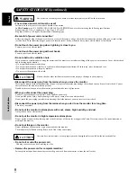
Page 3: ...e monitor If you drop water or a foreign substance on to the monitor it may cause fire or an electric shock If it happens turn off the monitor and disconnect the power plug from the mains and ask service center for instruction Do not put the monitor on an unstable place If you put the monitor on an uneven or unstable place it may fall down and you may be injured Put the monitor on a flat surface s...

Page 4: ...may cause serious injury or damage to your property CAUTION Disconnect the power plug from the mains when you move the monitor Moveing the monitor without disconnecting the power plug from the mains may damage the cord and cause a fire or electric shock You are advised to move the monitor with two persons Handle with care when you move the monitor particularly take care of glass screen When you di...

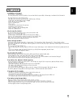
Page 5: ...sh them at appropriate intervals of time Turn down the contrast and brightness controls How to clean the monitor Before cleaning the monitor turn off the monitor and disconnect the power plug from the mains When cleaning the monitor do not spray directly the screen or cabinet with cleaner Use a clean dust free dry and soft cloth If it is not enough then use a cloth with non alcoholic or non ammoni...

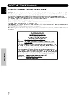
Page 6: ... are met Video inputs The input signal amplitude must not exceed the specified level CAUTION Changes or modifications not expressly approved by the party responsible for compliance could void the user s authority to operate the equipment Declaration of Conformity According to 47CFR Part 2 and 15 for Class B Personal Computers and Peripherals and or CPU Boards and Power Supplies used with Class B P...

Page 7: ... the future Notes on Installation Work This product is marketed assuming that it is installed by qualified personnel with enough skill and competence Always have an installation specialist or your dealer install and set up the product Dukane cannot assume liabilities for damage caused by mistake in installation or mounting misuse modification or a natural disaster Note for Dealers After installati...

Page 8: ...iating design greatly improves environmental operating conditions The thinner lighter design coupled to high endurance construction greatly broadens the range of possible installation locations and styles High reliability for commercial applications The is provided with features giving it high dependability in commercial applications including the ability to suppress peak luminance in accordance w...

Page 9: ...m 14 Setup after Connection 14 Operations 16 Selecting an Input Source 16 Screen Size Selection 18 Partial Image Enlargement POINT ZOOM 19 Automatic Power OFF 20 Display Panel Adjustments 21 Adjusting the Picture Quality 21 Adjusting the Image Position and Clock Automatic Adjustment 22 Manual Adjustment of Screen Position and Clock 23 Other Operations 24 Rewriting the Input Display INPUT LABEL 24 ...

Page 10: ...llation of the plasma display and connections to a wide variety of components The section Setting Up the System starting on page 14 covers the necessary on screen menu settings to establish correct linkage between the plasma display and connected components Depending on the connections made this section may or not be necessary The remainder of the sections in this manual is dedicated to the basic ...

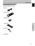
Page 11: ...re Proceeding Checking Supplied Accessories Check that the following accessories were supplied 1 Power cord 2 Remote control unit 3 AA R6 batteries x 2 4 Speed clamps x 2 5 Bead bands x 2 Before Proceeding USER S MANUAL ...

Page 12: ...age 16 4 INPUT button Press to select input page 16 5 MENU button Press to open and close the on screen menu pages 14 to 26 6 ADJUST 5 3 2 buttons Use to navigate menu screens and to adjust various settings on the unit Usage of cursor buttons within operations is clearly indicated in the on screen display pages 14 to 26 7 SET button Press to adjust or enter various settings on the unit pages 14 to...

Page 13: ...e the remote control Do not use the remote control unit in a location subject to direct sunlight heat radiation from a heater or in a place subject to excessive humidity When the remote control unit s batteries begin to wear out the operable distance will gradually become shorter When this occurs replace all batteries with new ones as soon as possible Inserting the batteries in the remote control ...

Page 14: ... that the connection made corresponds to the format of the signal output from the connected component pages 9 to 11 If you are having difficulty with operation of the remote control unit The remote control unit may not operate if there are objects placed between it and the display Operational distance will gradually become shorter as the batteries begin to wear out replace weak batteries with new ...

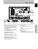
Page 15: ...tput jack of components connected to INPUT1 or INPUT2 to this unit page 11 0 AUDIO OUTPUT Stereo mini jack Use to output the audio of the selected source component connected to this unit to an AV amplifier or similar component page 11 1 2 3 4 5 6 7 89 0 L IN OUT CONTROL COMBINATION IN OUT RS 232C ANALOG RGB ANALOG RGB INPUT1 OUTPUT G B R HD VD ON SYNC H V SYNC Ô 75 2 2 Ω kΩ INPUT INPUT1 2 OUTPUT A...

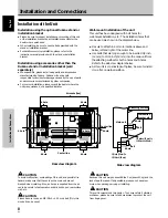
Page 16: ...ure to attach in 4 or more locations above and below left and right of the center line Use bolts that are long enough to be inserted 1 2 inch 12 mm to 11 16 inch 18 mm into the main unit from the attaching surface for both a holes and b holes Refer to the side view diagram below As this unit is constructed with glass be sure to install it on a flat unwarped surface CAUTION Because this unit weighs...

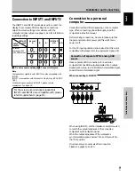
Page 17: ...jack Connection to a personal computer Connection method differs depending on the computer type When connecting please thoroughly read the computer s instruction manual Before making connections be sure to make sure that the personal computer s power and this unit s main power is off For the PC input signals and screen sizes that this unit is compatible with please refer to supplement 1 page 31 Co...

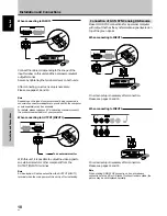
Page 18: ...GB INPUT1 OUTPUT With this unit it is possible to output the video signal to an external monitor or other component from the OUTPUT INPUT1 terminal Note A video signal will not be output from the OUTPUT INPUT1 terminal when the main power of this unit is off or in standby To an external monitor Connection of G ON SYNC analog RGB source Make G ON SYNC connections for a personal computer with output...

Page 19: ...omponent s power and the unit s main power is off Connecting the speakers This unit is equipped with speaker output jacks for connection to the speaker system not supplied specially designed for use with this unit Refer to the illustrations below when making connections to the speaker terminals on this unit 10 mm Note When making speaker connections be sure to match the polarities and of the speak...

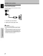
Page 20: ...wer supply voltage other than that indicated AC 100 120 V 50 60 Hz as this may cause fire or electric shock For the plasma display a three core power cord with a ground terminal is used for efficiency protection Always be sure to connect the power cord to a three pronged grounded outlet and make sure that the cord is properly grounded If you use a power source converter plug use an outlet with a g...

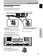
Page 21: ...amp Speed clamps are designed to be difficult to undo once in place Please attach carefully To attach the speed clamps to the main unit Connect the speed clamps using the 4 holes marked with below depending on the situation To remove speed clamps Using pliers twist the clamp 90 and pull it outward In some cases the clamp may have deteriorated over time and may be damaged when removed As viewed fro...

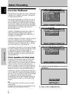
Page 22: ...ollow the procedure described below and make settings as they apply to the type of components connected Screen Mode setup Note These settings are required only when using the following input signal refresh rates 1 31 5 kHz horizontal 60 Hz vertical 2 48 4 kHz horizontal 60 Hz vertical or 56 5 kHz horizontal 70 Hz vertical No manual setup is necessary for signals with other refresh rates since adju...

Page 23: ... A I NP UT I NP UT 1 L E B L A MAIN MENU INPUT1 3 Press 5 to select CLAMP POSITION SELECT CHANGE EXIT SET MENU PICTURE SCREEN SET UP OPTION NT S E T T I N CL AMP POWE R G OF F P S I T I ON O M NAGEME A I NP UT I NP UT 1 L E B L A V GA A U TO MAIN MENU INPUT1 4 Press SET to select LOCKED SELECT CHANGE EXIT SET MENU PICTURE SCREEN SET UP OPTION NT S E T T I N CL AMP POWE R G OF F P S I T I ON O M NA...

Page 24: ...nal input will cause the menu screen to turn off If the input computer signal is not supported by the display the following message will be displayed 0 8 5 5 1 2 6 8 4 k H z f V 1 7 1 7 H z f H P O U SUP N S R ED T I NAL G CAU I O N T FUL L I NPUT 1 X 0 2 0 k H z f V 7 7 1 5 H z f H T OU N O A R F G E CAU I O N T FUL L I NPUT 1 4 Use VOLUME on the remote control unit to adjust the volume If no aud...

Page 25: ...tomatically canceled about 8 minutes after the button is pressed and the volume level is adjusted to the minimum level Press VOLUME or VOLUME to adjust the volume at a desired level To confirm display settings DISPLAY Press DISPLAY on the remote control unit The currently selected input screen size and refresh rates will be displayed for about 3 seconds O D BY T DOT I NPUT 1 0 6 0 4 6 0 8 4 0 k H ...

Page 26: ...en sizes described in the table on this page Press SCREEN SIZE to select the size The screen size changes each time SCREEN SIZE is pressed as follows Consult the table Computer Signal Formats Supported page 31 for information regarding screen sizes supported by each signal format Notes When the PARTIAL or FULL setting is used to display a non wide screen 4 3 picture fully on a wide screen a portio...

Page 27: ...aken for three seconds or more the display screen will disappear SET or 5 2 3 can be pressed again if desired to change the zoom ratio or display position 4 Press the remote control unit s POINT ZOOM once again to cancel the point zoom operation The point zoom function will also be canceled whenever the input signal changes the menu screen is displayed or the INPUT changes Note Whenever point zoom...

Page 28: ...N AU T O S E T T I N CL AMP POWE R G OF F P S I T I ON O M NA GEME A I NP UT I NP UT 1 L E B L A V GA NT MAIN MENU INPUT1 When using INPUT 2 PICTURE SCREEN SET UP OPTION V GA AU T O S E T T I N CL AMP A UTO POWE R G OF F OF F P S I T I ON O I NP UT I NP UT 2 L E B L A MAIN MENU INPUT2 4 Press SET to confirm selection of the POWER MANAGEMENT or AUTO POWER OFF When OFF is selected the display will c...

Page 29: ...s PICTURE mode adjustment items Below are brief descriptions of the options that can be set in the PICTURE mode CONTRAST Adjust according to the surrounding brightness so that the picture can be seen clearly BRIGHT Adjust so that the dark parts of the picture can be seen clearly R LEVEL Adjust the amount of red in the picture G LEVEL Adjust the amount of green in the picture B LEVEL Adjust the amo...

Page 30: ...erform this adjustment individually for each input function INPUT 1 INPUT 2 and each signal type Press AUTO SET UP on either the main unit or remote control unit Optimum settings may not be possible for low luminance and certain other kinds of signals In this case following the instructions in the following section Manual Adjustment of Screen Position and Clock to make more precise adjustments AUT...

Page 31: ...ow are brief descriptions of the options that can be set in the SCREEN mode POSITION H POSITION Adjust the picture s position to the left or right V POSITION Adjust the picture s position upward or downward CLOCK PHASE CLOCK Adjust letter breakup or noise on the screen This setting adjusts the unit s internal clock signal frequency that corresponds to the input video signal PHASE Adjust so that th...

Page 32: ...E B L A T E S RE D N E A E C A S P MAIN MENU INPUT1 5 Press 2 3 5 to select the first desired character here C then press SET to confirm repeat this step to input up to eight desired characters SELECT SET EXIT SET MENU BACK SPACE J M K L B C D E F G H W Z X Y N O P Q R S T V U 9 0 1 2 3 4 5 6 8 7 I NP UT I NP UT 1 L E B L A T E S RE E C A S P D N E A C I MAIN MENU INPUT1 Usable characters include ...

Page 33: ...ARD setting but at a even lower levels of power consumption MODE 2 fixes the screen brightness regardless of the input signal This is effective at reducing panel deterioration due to screen burning 4 Following completion of settings press MENU to return to normal screen display Note The POWER CONTROL setting affects all input sources AUTO FUNCTION This display is equipped with an optional AUTO FUN...

Page 34: ...O OUT The signal level produced at the AUDIO OUT jack can be set to FIXED or VARIABLE linked to the VOLUME as desired 1 Press MENU The onscreen menu will be displayed MAIN MENU INPUT1 SELECT ENTER EXIT SET MENU PICTURE SCREEN SET UP OPTION 0 6 0 6 0 6 0 0 0 CONT RAST 0 BR R L EV EL I GHT G L EV EL B L EV EL H E NHANCE V E NHANCE R S ET E 2 Press 2 3 to select OPTION SELECT CHANGE EXIT SET MENU PIC...

Page 35: ...ubleshooting What may at first seem to be an malfunction may be remedied with a quick check Please check to see if a warning is displayed on the screen If displayed refer to the table below and check the mode If there is no display check to see if the problem is listed on page 28 The problem may also be caused by something other than this unit so please also check the other components being used s...

Page 36: ...tions of image appear to be losing intensity Speckles or noise appears on screen Stripes appear on the screen Operation is not possible Sound is heard from inside the unit Fan isn t moving Fan speed changes Check the input signal compatibility chart page 31 Is the correct screen size selected pages 18 22 and 23 Adjust using SCREEN mode on the menu screen page 23 If there is still no improvement th...

Page 37: ...DBY ON is pressed to set the unit to the standby mode the indicator will flash red for several seconds page 16 Other than this if the power turns off by itself or refuses to turn on or if the red indicator conditions flashing a malfunction may be indicated Immediately disconnect the power plug and consult your dealer or a service center Additional Information About the plasma panel s protection fu...

Page 38: ...ay VESA DDC1 2B Output Mini D sub 15 pin socket connector 75 Ω with buffer INPUT 2 Input BNC jack x5 RGB signal G ON SYNC compatible RGB 0 7 Vp p 75 Ω no sync HD CS VD TTL level positive and negative polarity 75 Ω or 2 2 kΩ impedance switch G ON SYNC 1 Vp p 75 Ω negative sync Additional Information Audio Input AUDIO INPUT for INPUT 1 2 Stereo mini jack L R 500mVrms more than 10 kΩ Output AUDIO OUT...

Page 39: ...1kHz 46 9kHz 53 7kHz 49 7kHz 31 7kHz 48 4kHz 56 5kHz 60 0kHz 60 2kHz 68 7kHz 53 7kHz 64 9kHz 67 7kHz 68 7kHz 61 8kHz 71 7kHz 45 1kHz 48 4kHz 55 5kHz 60 0kHz 64 0kHz 80 0kHz 91 1kHz 75 0kHz 81 3kHz 87 5kHz 93 8kHz 106 3kHz 1024x768 1024x768 1024x768 1024x768 1016x768 984x768 1024x768 960x768 1024x768 640x480 800x600 832x624 852x480 1024x768 1280x768 4 3 NEC PC 9800 NEC PC 9800 852x480 864x480 Apple...

Page 40: ...Supplement 2 Signal assignment of INPUT 1 Mini D sub 15 pin socket connector Input Output 1 2 3 4 5 6 7 8 9 10 11 12 13 14 15 R or CR PR G or Y B or CB PB NC No connection GND GND GND GND DDC 5V GND NC No connection DDC SDA HD or H V SYNC VD DDC SCL NC No connection NC No connection NC No connection 5 1 15 11 6 10 Pin No Apple and Macintosh are registered trademarks of Apple Computer Inc Microsoft...

Page 41: ...oration disclaims all liability for incidental or consequential damage of any kind including all damages arising out of any interruptions in operation of the product and all damages to software No person firm or representative is authorized to assume any obligation or to make any warranty on behalf of the Dukane Corporation other than as stated above THIS LIMITED WARRANTY IS VALID FOR U S A AND CA...

Page 42: ... Division 2900 Dukane Drive St Charles IL 60174 3395 E mail avsales dukane com Phone 630 584 2300 Orders 800 676 2485 Information 800 676 2486 Fax 630 584 5156 Parts Service 800 676 2487 Fax 630 584 0984 Audio Visual Products Part 401 593 00 ...

Reviews: