12
SUPPORT STRUCTURE
ORIENTATION CONTINUED
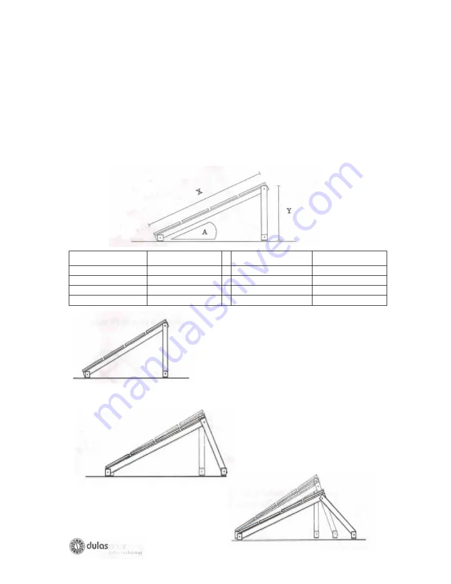
The support structure is made from pre-drilled galvanized steel angle. If you
mounting area cannot be level e.g. you have a sloping roof, then adjusting the foot
mounting holes must make the correct angle.
Use the ratios below to calculate your appropriate angle and follow the diagram to
position the structure accurately.
Required angle (A) Approx. ratio (x:y) Required Angle (A)
Approx. ratio(x: y)
10
0
6:1
30
0
2:1
15
0
4:1
35
0
1.75:1
20
0
3:1
40
0
1.5:1
25
0
2.4:1
45
0
1.4:1
Changing the position or length of the Tilt legs
can alter module angles.
Always ensure that all bolts are secured
tightly after alterations have been made.
A protractor can be used to determine
if the correct angle has been acquired.
Summary of Contents for VC150
Page 1: ......
Page 3: ...3 SECTION I ...
Page 4: ...4 ...
Page 24: ...24 MODULE AND BATTERY WIRING DIAGRAMS SYSTEM WIRING DIAGRAM ...
Page 25: ...25 SYSTEM WIRING DIAGRAM GENERAL LAYOUT DIAGRAM ...
Page 26: ...26 GENERAL LAYOUT DIAGRAM ELECTRICAL CIRCUIT DIAGRAM ...
Page 27: ...27 ELECTRICAL CIRCUIT DIAGRAM REFRIGERATION CIRCUIT DIAGRAM ...
Page 28: ...28 REFRIGERATION CIRCUIT DIAGRAM ...
Page 29: ...29 SECTION II ...
Page 38: ...38 ...
Page 39: ...39 ...
Page 42: ...42 ...
Page 44: ...44 ...
Page 50: ...50 ...
Page 124: ...124 ANNEX 1 COMPONENT LAYOUTS OF SOME COMMONLY USED SOLAR REFRIGERATOR ...
Page 125: ...125 ...
Page 126: ...126 ...
Page 127: ...127 ...
Page 128: ...128 ...
Page 129: ...129 ...
Page 130: ...130 ANNEX II ADDITIONAL EPI TOOL KIT NEEDED FOR PHOTOVOLTAIC REFRIGERATOR REPAIR ...
Page 136: ...136 ...
Page 137: ...137 ...


