www.factorybuysdirect.com
200423-01A
15
INSTALLATION
Note: Frame parts have a protective film to protect the pieces during shipment. The protective film must be
removed before operating the appliance. Only remove film as needed during assembly to protect the front
facing surfaces of the parts from being scratched. If removing the protective film is necessary, place parts on a
smooth surface.
REMOVABLE FRONT FRAME ASSEMBLY
1.
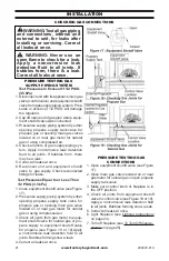
Unpack and Identify each Frame part
shown in Figure 10.
2.
Remove the protective film as needed
from the visible surfaces.
3.
Arrange all frame parts, except the
screen rod cover, face down in the pre-
assembled orientation on a protected
surface (i.e. using Cardboard / Foam
Packaging) as shown in Figure 10.
4.
Assemble the Top, Sides and Middle
Frame Parts using a No. 2 Phillips screw
driver with 3/8 Wrench; 8 - Nuts, Screws
and Washers, as shown in Figure 10.
5.
Install the Control Access Door in position
shown in Figure 10, using 2 -Screws and
Washers in combination with 1 - Hinge
Pin into each Side Frame using a No. 2
Phillips Screw Driver. See Figure 10.
Inspect Contents of Hardware Pack:
14 Qty. - 3/8" Hex Nuts 8-32
18 Qty. - Screws, #8-32 Phillips Head
18 Qty. - Lock Washers #8
2 Qty. - Hinge Pins
Hint:
Thread 1 screw with washer into
one end of each Hinge Pin, (See Detail in
Figure 10.), then insert the open end of the
Hinge Pin through the pivot hole located on
the lower inside of the Access Door, align
with the mounting hole on the outer Side
Face Frame and thread another screw and
washer. Finish tighten from the inside screw
to secure each Pin assembly.
6.
Install the Hood to the lower edge of the
Top Frame using the same tools in used
in Step 4. See Figure 10 for correct hood
position.
7.
Install the Screen Rod Cover using the
same tools with 2 - Screws, Nuts and
Washers, see Detail in Figure 11 for cor
-
rect position.
8.
Attach the frame assembly to the
fireplace by aligning the notches on the
sides of the frame over the 4 mounting
pins located on the inside of the fireplace
cabinet and slide the frame assembly
down to lock the notches onto each pin.
See Figure 12.
3/8 Hex Nut
QTY. 12
TOP FRAME
HOOD
Screw # 8-32
#2 Phillips
QTY. 12
#8 Lock
Washer
QTY. 12
LEFT FRAME
CONTROL
ACCESS
DOOR
Screw # 8-32
#2 Phillips
QTY. 4
2 Each Side
Hinge Pin
QTY. 2
#8 Lock
Washer QTY. 4
2 Each Side
MIDDLE FRAME
RIGHT FRAME
Figure 10 - Front Frame, Hood and Door Assembly


