background image

www.factorybuysdirect.com

200257-01A

10

Gas Inlet / Gas esté

INLET GAS PRESSURE MAX 1/2 PSIG (3.5 KPa)

200110-01B

03/15

WARNING: 

Make sure Regulator Cap is in the appropriate position 

as shown in diagrams. Installation and service should be done by 

qualified service technician only.

Natural Gas

When using natural gas:

   Make sure the cap is installed in the propane/LP inlet of regulator.


Use thread sealant to assure there are no leaks.

Propane/LP Gas

When using propane/LP gas:

   Make sure the cap is installed in the natural gas (NG) inlet of regulator.


Use thread sealant to assure there are no leaks.

ADVERTENCIA: 

Asegúrese la tapa del regulador esté en la posición adecuada, 

como se muestra en los diagramas. La instalación y reparaciones deben ser realizadas 

por un técnico de servicio calificado solamente.


Gas Natural 

Cuando se utiliza gas natural: 

   Asegúrese de que la tapa está instalado en el propano/LP entrada del regulador. 

   Utilice sellador de roscas para asegurar que no haya fugas. 

Propano/LP Gas 

Cuando se utiliza el gas propano / LP: 

    Asegúrese de que la tapa está instalado en la entrada de gas natural (GN) del regulador. 

    Utilice sellador de roscas para asegurar que no haya fugas.

Correct Pilot Flame Pattern

Incorrect Pilot Flame Pattern

NG

3-3.5" WC

Natural Gas

Shown

LP

8-11" WC

NG

3-3.5" WC

Natural Gas

Shown

LP

8-11" WC

1/2 Glass

Height

1/2 Glass

Height

Yellow

Tipping

Correct Burner Flame Pattern

Incorrect Burner Flame Pattern

LP

Blue Plunger

INSTALL SUPPLIED CAP IN FITTING

NOT BEING USED.

INSTALAR TAPA SUMINISTRADA MONTAJE NO SE UTILIZA.

NG

Yellow Plunger

This appliance may be installed in an aftermarket,* 

permanently located, manufactured (mobile) home, where 

not prohibited by local codes.

This appliance is only for use with propane or natural gas.

Field conversion by any other means including the use of 

a kit is not permitted.

WARNING: Make sure the supplied cap is 

installed in unused regulator fitting before 

connecting the correct gas supply line. 

WARNING: Do not use natural gas and 

propane gas together.

CAUTION: Two gas line installations at 

the same time are prohibited.
ADVERTENCIA: Asegúrese de que la línea 

no utilizado se conecta por primera vez 

antes de conectar la línea de suministro 

de gas correcta. 

ADVERTENCIA: No utilice el gas natural y 

el gas propano juntos.

PRECAUCIÓN: Dos instalaciones de 

líneas de gas al mismo tiempo están 

prohibidos.

FOR PROPANE GAS SUPPLY

PARA LA FUENTE DE GAS DEL PROPANE

CAUTION: The heater requires an external regulator to reduce 

the LP tank pressure to a maximum of 14" W.C. Never connect 

this product directly to the supply tank.
PRECAUCIÓN: El calentador requieres una externa regulador 

para reducir la presión del tanque de gas a un máximo de 14" 

W.C. Nunca conecte este producto directamente al tanque de 

suministro.

FOR NATURAL GAS SUPPLY

PARA LA FUENTE DE GAS DEL NATURAL

NOTICE: An additional gas regulator will be necessary if the 

local natural gas pressure exceeds the heater's rated maximum 

inlet pressure. If in doubt, contact the local gas utility. If natural 

gas inlet pressure exceeds 10" W.C., the safety pressure switch 

will activate. See owners manual for proper procedure to bypass 

the pressure switch.
AVISO: Un regulador de gas adicional será necesario si la 

presión del gas natural local excede de entrada nominal máxima 

del calentador presión. En caso de duda, póngase en contacto 

con la compañía de gas local. Si la presión de entrada de gas 

natural supera los 10" WC, el interruptor de presión de 

seguridad se activará. Consulte el manual del propietario para el 

procedimiento adecuado de derivación el interruptor de presión.

Procom Heating, Inc. U.S. Patent Information

This product may be covered by one or more of the following

United States patents:

8,915,239   8,851,065   8,764,436   8,757,202   8,757,139   8,752,541   

8,568,136   8,545,216   8,517,718   8,516,878   8,506,290   8,465,277   

8,317,511   8,297,968   8,281,781   8,241,034   8,235,708   8,152,515   

8,011,920   7,967,006   7,967,007   7,654,820   7,730,765   7,677,236   

7,607,426   7,434,447

Other patents pending.

TOLL-FREE Customer Care Number: 1-866-573-0674

Numero de Atención al Cliente GRATUITO: 1-866-573-0674

Visit our website for more information www.usaprocom.com

Visite nuestra página web para más informacion www.usaprocom.com

INSTALLATION

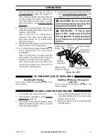
Figure 8 - Back of Stove

Gas Connection

Yellow Natural Gas 

Plunger Underneath 

Metal Cap

Blue Propane/LP Gas 

Plunger Underneath 

Dust Cover

Figure 9 - Gas Regulator

Insert Gas Fitting 

for Natural Gas

Insert Gas Fitting 

for Propane/LP Gas

Fitting supplied with the product located in 

the hardware bag. Fitting part number:

160960-02 (straight)

160960-03 (elbow)

Blue Dust Cover

DO NOT REMOVE

Blue Propane/LP Plunger

Install Gas Fitting Here

GAS SELECTION

This appliance is factory 

preset for propane/LP gas. 

No changes are required for 

connecting to propane/LP.


Only a qualified installer or service 

technician can perform gas selec-

tion and connecting to gas supply.

 CAUTION: Two gas line in-

stallations at the same time are 

prohibited.

 CAUTION: To avoid gas leak-

age for the gas not being used at 

the inlet of regulator, a qualified 

installer  or  service  technician 

must use supplied cap.
You will notice a color coded 

plunger on the inside of the regu-

lator. This is normal. When the in-

let connection fitting is inserted 

and tightened, this plunger will 

be  pushed  back  by  the  fitting 

making  all  of  the  adjustments 

for the gas being supplied. DO 

NOT REMOVE THE PLUNGER. 

The regulator will not work.

The inlet regulator is color coded 

for identification of the correct 

gas type. Blue is for propane (LP 

gas) and yellow is for natural gas.

FOR PROPANE/LP GAS 

INSTALLATION: BLUE

1.  Remove blue dust cover.

Summary of Contents for FDSR25

Page 1: ...cal switch do not use any phone in your building Immediately call your gas supplier from a neighbor s phone Follow the gas supplier s instructions If you cannot reach your gas supplier call the fire department Installation and service must be performed by a quali fied installer service agency or the gas supplier WARNING This appliance is equipped for natural and propanegas Fieldconversionisnotperm...

Page 2: ...ING Improper installation adjustment al teration service or maintenance can cause injury or property damage Refer to this manual for correct in stallation and operational procedures For assistance or additional information consult a qualified installer service agency or the gas supplier This appliance may be installed in an aftermarket per manently located manufactured mobile home where not prohib...

Page 3: ...lude pregnant women people with heart or lung disease or anemia those under the influ ence of alcohol and those at high altitudes NATURALAND PROPANE LP GAS Natural and Propane LP gas are odorless An odor making agent is added to the gas The odor helps you detect a gas leak However the odor added to the gas can fade Gas may be present even though no odor exists WARNING Any change to this stove or i...

Page 4: ...uld service and repair stove 10 Operating stove above elevations of 4 500 feet could cause pilot outage 11 To prevent performance problems do not use propane LP fuel tank of less than 100 lbs capacity 12 Do not use this stove as a wood burning stove Use only the logs provided with the stove 13 Solid fuels should not be burned in a stove in which a vent free log set is installed Do not use this sto...

Page 5: ...ctory ready for connect ing to Propane LP The stove can easily be changed to Natural gas by having your quali fied installer follow the instructions on page 10 and the markings on the stove MANUAL OVERRIDE CONTROL SYSTEM This stove has two operation functions Re mote Control and Manual Override Control The remote control has a transmitter which requires twoAAAbatteries and electric power outlet to...

Page 6: ...l help ensure that water vapor does not become a problem 1 Be sure the heater is sized properly for the application including ample combustion air and circulation air 2 If high humidity is experienced a dehu midifier may be used to help lower the water vapor content of the air 3 Do not use an unvented room heater as the primary heat source UNPACKING 1 Remove top inner pack 2 Tilt carton so that st...

Page 7: ...rning appli ances WARNING This heater shall not be installed in a room or space unless the required vol ume of indoor combustion air is provided by the method de scribed in the National Fuel Gas Code ANSI Z223 1 NFPA 54 the International Fuel Gas Code or applicable local codes WARNING Iftheareainwhich theheatermaybeoperateddoes notmeettherequiredvolumefor indoorcombustionair combus tion and ventil...

Page 8: ...llthisstoveasyourprimary heat source If you have a cen tral heating system you may run system s circulating blower while using stove This will help circulatetheheatthroughoutthe house In the event of a power outage you can use this stove as your primary heat source WARNING A qualified ser vice person must install stove Follow all local codes WARNING ElectricalGround ingInstructions Ifusingablower ...

Page 9: ... the heater s rated maximum inlet pressure If in doubt contact the local gas utility If natural gas inlet pressure exceeds 10 W C the safety pressure switch will activate See owners manual for proper procedure to bypass the pressure switch AVISO Un regulador de gas adicional será necesario si la presión del gas natural local excede de entrada nominal máxima del calentador presión En caso de duda p...

Page 10: ...imo de 14 W C Nunca conecte este producto directamente al tanque de suministro FOR NATURAL GAS SUPPLY PARA LA FUENTE DE GAS DEL NATURAL NOTICE An additional gas regulator will be necessary if the local natural gas pressure exceeds the heater s rated maximum inlet pressure If in doubt contact the local gas utility If natural gas inlet pressure exceeds 10 W C the safety pressure switch will activate...

Page 11: ...ntil the threads engage the regulator After the fitting has been hand tightened into the regulator use a wrench to complete tightening of the fitting Install additional fitting to connect to the house supply FOR NATURAL GAS NG INSTALLATION YELLOW 1 Remove the blue dust cover from the regulator 2 Remove the metal cap installed over the NG regulator inlet 3 Install metal cap over LP Propane regulato...

Page 12: ...s line Gas line pressure must be no greater than 9 of w c If gas line pressure is higher stove regulator damage could occur CAUTION Avoid damage to regulator Hold gas regulator with wrench when connecting into gas piping and or fittings CAUTION Use pipe joint sealant that is resistant to gas Propane LP or Natural Gas Before installing stove make sure you have the items listed below external regula...

Page 13: ...he local natural gas pressure exceeds the heater s rated maximum inlet pressure If in doubt contact the local gas utility If natural gas inlet pressure exceeds 10 W C the safety pressure switch will activate See owners manual for proper procedure to bypass the pressure switch AVISO Un regulador de gas adicional será necesario si la presión del gas natural local excede de entrada nominal máxima del...

Page 14: ...all leaks at once 6 Reconnect stove and equipment shutoff valve to gas supply Check reconnected fittings for leaks Test Pressures Equal To or Less Than 1 2 PSIG 3 5 kPa 1 Close equipment shutoff valve see Fig ure 13 2 Pressurize supply piping system by either opening propane LP supply tank valve for propane LP gas or opening main gas valve located on or near gas meter for natural gas or using comp...

Page 15: ...tery installa tion may void the warranty on the product For remote control systems maximize bat tery life by turning off the receiver when it is not in use For long periods of non operation remove batteries from all components for safety Component Type of Battery Qty Ignitor AAA 1 Remote Control AAA 2 or 3 Remote Receiver AA 4 Note Quantity depends on model of remote control Ignitor Unscrew ignito...

Page 16: ...cket 3 Place pins on log 2 into slots in the middle bracket 4 Place pins on log 3 into slots the front bracket WARNING Failure to posi tion the parts in accordance with these diagrams or failure to use only parts specifically approved with this stove may result in property damage or personal injury CAUTION After installation and periodically thereafter check to ensure that no flame comes in contac...

Page 17: ... 2 with one end resting on log 3 6 Install hole in log 5 onto pin on the right side of log 1 with one end resting on log 2 7 Install hole in log 6 onto the pin on the right side of log 3 IMPORTANT Make sure logs do not cover any burner ports It is very important to install the logs exactly as instructed Do not modify logs Use only logs supplied with stove ...

Page 18: ...en are installed before running stove NOTICE Duringinitialoperationof new stove burning logs will give offapaper burningsmell Orange flame will also be present Open damper or window to vent smell This will only last a few hours 1 STOP Read the safety information above 2 Turn handle and open stove door 3 Make sure equipment shutoff valve is fully open 4 Push in control knob slightly and turn clockw...

Page 19: ...control valve to reset before starting again 11 If stove will not operate follow the instruc tions To Turn Off Gas To Appliance and call your service technical or gas supplier CAUTION Do not try to ad just heating levels by using the equipment shutoff valve WARNING If input gas type is NG make sure NG pilot burner ignites If input gas type is LP make sure LP pilot burner ignites Shutting Off Heate...

Page 20: ...the slide switch on the receiver can be used to operate the stove Note When batteries are replaced the learning process above must be repeated LEARN REMOTE OFF ON Figure 21 Receiver Slide Switch Learn Button Key Settings ON Operates unit to on position manually operated solenoid ON OFF Operates unit to off position manually operated solenoid OFF MODE Changes unit from manual mode to thermo mode SE...

Page 21: ...D screen will display the set temperature for 3 sec onds then flash the set temperature for 3 seconds then LCD screen will default to display the room temperature To Change The Set Temperature 1 Press and hold the SET key until the desired set temperature is reached The LCD screen set numbers will increase from 45 to 99 then restart over at 45 2 Release the SET key The LCD screen will display the ...

Page 22: ...oubleshooting pages 26 through 29 WARNING If yellow tipping occurs the pilot should be cleaned Notice Do not mistake orange flames with yellow tipping Dirt or other fine particles enter the stove and burn causing brief patches of orange flame Approx 3 6 Above Top of Logs More Than 8 Above Top of Logs Approx 3 6 Above Top of Logs More Than 8 Above Top of Logs Figure 28 Correct Burner Flame Pattern ...

Page 23: ...D PILOT AIR INLET HOLE We recommend that you clean the unit ev ery 2 500 hours of operation or every three months We also recommend that you keep the burner tube and pilot assembly clean and free of dust and dirt To clean these parts we recommend using compressed air no greater than 30 PSl Your local computer store hardware store or home center may carry compressed air in a can You can use a vacuu...

Page 24: ...properly replace logs Replace log s if broken or chipped dime size or larger ELECTRICAL ELECTRICAL CONNECTION FOR STOVES EQUIPPED WITH A BLOWER Do not use this stove if any part of it has been under water Immediately call a qualified ser vice technician to inspect the stove and replace any part of the electrical system which has been under water GROUNDING INSTRUCTIONS This stove is for use on 120 ...

Page 25: ...l calentador requieres una externa regulador para reducir la presión del tanque de gas a un máximo de 14 W C Nunca conecte este producto directamente al tanque de suministro FOR NATURAL GAS SUPPLY PARA LA FUENTE DE GAS DEL NATURAL NOTICE An additional gas regulator will be necessary if the local natural gas pressure exceeds the heater s rated maximum inlet pressure If in doubt contact the local ga...

Page 26: ... the operation of the unit on the wrong gas propane LP If your natural gas supply exceeds 9 WC the unit will not operate Either contact your gas supplier to check and adjust the inlet pressure or a qualified service technician can bypass the pressure switch Before attempting to bypass the pressure switch make sure the type of gas being used is correct Check to make sure the connection fitting is i...

Page 27: ...in control knob while pressing ignitor button 3 Continue holding down con trol knob Repeat igniting op eration until air is removed 4 Clean ODS pilot see Care and Maintenance page 23 or replace ODS pilot assembly 5 Check inlet gas pressure or replace inlet gas regulator 6 Turn control knob to PILOT position 7 Contact local propane LP gas company ODS pilotlightsbutflame goes out when control knob i...

Page 28: ...etween control valve and burner 2 Gas leak See Warning Statement at top of page 26 1 Take apart gas tubing and remove foreign matter 2 Locate and correct all leaks see Checking Gas Connec tions page 14 Slight smoke or odor during initial operation 1 Residues from manufactur ing process 1 Problem will stop after a few hours of operation Heater produces a whis tling noise when burner is lit 1 Turnin...

Page 29: ...2 Control valve is defective 1 Locate and correct all leaks see Checking Gas Connec tions page 14 2 Replace control valve Moisture condensation noticed on windows 1 Not enough combustion ventilation air 1 Refer to Air for Combus tion and Ventilation require ments page 7 SERVICE HINTS When Gas Pressure Is Too Low pilot will not stay lit burners will have delayed ignition stove will not produce spec...

Page 30: ...www factorybuysdirect com 200257 01A 30 PARTS MODEL FDSR25 FDSR25GF RE MOTE OFF ON LE AR N REM OTE OFF ON T E M P PILOT OFF ON PILOT OF F ON 1 6 14 13 3 7 4 10 15 17 18 16 11 12 5 2 8 9 ...

Page 31: ...rts Available Not Shown WYL601 01 Hardware Package 1 PCAM 012 AAA Battery 1 REPLACEMENT PARTS Note Use only original replacement parts This will protect your warranty coverage for parts replaced under warranty PARTS UNDER WARRANTY Contact authorized dealers of this product If they can t supply original replacement parts call Customer Service toll free at 1 855 607 6557 for referral information Whe...

Page 32: ...ost of part s required to restore this product to proper operating condition and an allowance for labor when provided by a Factory Buys Direct Authorized Service Center or a provider ap proved by Factory Buys Direct Warranty parts must be obtained through authorized dealers of this product and or Factory Buys Direct who will provide original factory replacement parts Failure to use original factor...

Reviews: