25
Pt. No. 67436
Issue 1119
Calibration via PRIMING SWITCH (continued)
3
The appropriate metering unit will run until the PRIMING
SWITCH is pressed again. Product is collected in this
time. The operator is in control of the amount of product
metered out so is able to stop the metering unit when
the collecting container is at a suitable fill level.
4
Weigh the contents of the container. Write down the
amount exactly as displayed. Do not round up or round
down the value measured.
Scales must be accurate to
2 grams.
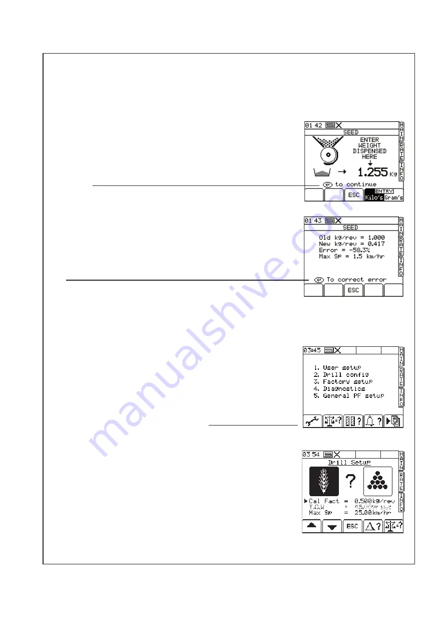
5
Enter the recorded value into the ProSeries head unit as
shown. Press ‘ENTER’ to confirm as requested.
Always use consistant units of measure ie grams or
Kilograms.
6
Press ‘ENTER’ again. The instrument will then calculate
the settings in order to correctly deliver the product. The
‘error’ value is only the difference between the new and
old settings. Subsequent recalibrations with the same
product will only report small differences.
7
Press ‘ENTER’ again to confirm and store the new
settings.
8
Repeat the calibration process. In this case, the ‘Error’
reported will be very small if any. Remember to press
the ‘ENTER’ key to accept the settings.
This repeat
calibration is especially important if the metering units
have been adjusted from very different values since the
last time the machine was used.
9
NOTE: If, when presing the priming switch the motors
do not turn but there are no other errors, it could be
that the previous calibration was wrongly entered. The
metering speed is out of the range of the motor speed.
This can be corrected by manually entering a ‘calibration
factor’ as follows:
(i) Press the ‘SETUP’ menu key.
(ii) Press the key below the wrench icon.
(iii) Use the up down left right arrows to select the
product. The left right arrows will appear when the
cursor is moved up one line from the ‘Cal Fact’.
(iv) Move the arrow to the ‘Cal Fact’ line, type 0.500
and hit the ‘ENTER’ key. (You need to enter the leading
zero as the machine will not accept the ‘.’ as a first
character.)
(v) Hit the ‘ESC’ key to return to the ‘SETUP’ menu or
hit the ‘MAIN’ key to return to the ‘MAIN’ menu.
(vi) Repeat the calibration process from step 1.
‘Renovator AS5300’
Calibration
Summary of Contents for Renovator AS5300
Page 2: ......
Page 7: ...5 Pt No 67436 Issue 1119 Renovator AS5300 Dimensions Capacities...
Page 16: ...14...
Page 24: ...22 Renovator AS5300 Read Before Operation...
Page 33: ...31 Pt No 67436 Issue 1119 Renovator AS5300 Calibration Notes...
Page 45: ...43 Pt No 67436 Issue 1119 Renovator AS5300 Notes...
Page 46: ...44...
Page 50: ...48 Left Hand Tine Shown 11 12 10 1 4 2 7 8 13 3 9 5 14 9 Renovator AS5300 Tine Boot Assembly 6...
Page 54: ...52 6 7 Renovator AS5300 Bushes Mainframe Wheels 5 4 3 2 1 8 10 9 11 See page 58 for lift rams...
Page 58: ...56 1 Renovator AS5300 Bushes Wing Pivot 3 4 2 5 6 4 2 11 7 7 5 8 3 10 4 2 5 3 9...


