26
Instruction Manual/Betriebsanleitung
BG 65 SI
, Version: 1.3 en_de
© 2010 Dunkermotoren GmbH; D-79848 Bonndorf; Germany
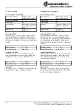
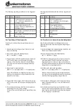
9.2 Function of the digital inputs IN1 and IN2
With the help of the two digital inputs IN1 and IN2,
altogether 4 operating conditions can be triggered,
because of the fact that to each of the both inputs the
logical states 0 and 1 are dedicated:
0 complies with an input level of 0 ... 6 V
1 complies with an input level of 7 ... 24 V
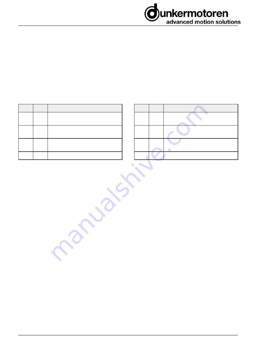
The following operating conditions can be triggered:
IN1
IN2
Function
0
0
Controlling not active, output stage not
provided with current, no holding torque
1
0
Counter clockwise rotation (motor
shaft turns counter clockwise)
0
1
Clockwise rotation (motor shaft
turns clockwise)
1
1
Stop with holding torque
9.3 Function of the digital inputs IN3 and IN4
In case the motor provides the option (inputs IN3, IN4
lead through), two fixed speed values can be adjusted
by “teaching”.
Note:
In the basic setting (delivery status ex works), 2 fixed
speed values spd1 and spd2 are preset:
spd1 = 200 rpm
spd2 = 2500 rpm
Furthermore, it can be toggled between motor speed
regulated mode (50 ... 4096 rpm) and unregulated de.
In unregulated mode, the motor can be operated up to
its maximum idle-running speed (approx. 6500 rpm).
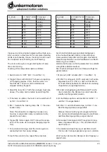
With the help of the two digital inputs IN3 and IN4,
altogether 4 operating conditions can be triggered,
because of the fact that to each of the both inputs the
logical states 0 and 1 are dedicated:
0 complies with an input level of 0 ... 6 V
1 complies with an input level of 7 ... 24 V
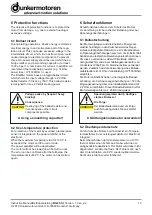
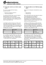
9.2 Funktion der Digitaleingänge IN1 und IN2
Mit Hilfe der beiden digitalen Eingänge IN1 und IN2
lassen sich insgesamt 4 Betriebszustände ansteuern,
da jedem der beiden Eingänge die logischen Zustän
-
de 0 und 1 zugeordnet sind:
0 entspricht einem Eingangspegel von 0 ... 6 V
1 entspricht einem Eingangspegel von 7 ... 24 V
Die folgenden Betriebszustände können angesteuert
werden:
IN1
IN2
Funktion
0
0
Reglersperre, Endstufe nicht
bestromt, kein Haltemoment
1
0
Linkslauf (Motorwelle dreht gegen
den Uhrzeigersinn)
0
1
Rechtslauf (Motorwelle dreht im
Uhrzeigersinn)
1
1
Stopp mit Haltemoment
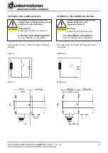
9.3 Funktion der Digitaleingänge IN3 und IN4
Falls der Motor die Option bietet (Eingänge IN3, IN4
herausgeführt), können zwei feste Geschwindigkeits-
werte eingestellt und abgespeichert (engl. „Teachen“)
werden.
Hinweis:
In der Grundeinstellung (Auslieferungszustand ab
Werk) sind bereits 2 feste Geschwindigkeitswerte
spd1 und spd2 voreingestellt:
spd1 = 200 rpm
spd2 = 2500 rpm
Darüber hinaus kann zwischen drehzahlgeregeltem
Betrieb (50 ... 4096 rpm) und ungeregeltem Betrieb
um-geschaltet werden. Im ungeregelten Betrieb kann
der Motor bis zu seiner maximalen Leerlaufdrehzahl
(ca. 6500 rpm) betrieben werden. Mit Hilfe der beiden
digitalen Eingänge IN3 und IN4 lassen sich insgesamt
4 Betriebszustände ansteuern, da jedem der beiden
Eingänge die logischen Zustände 0 und 1 zugeordnet
sind:
0 entspricht einem Eingangspegel von 0 ... 6 V
1 entspricht einem Eingangspegel von 7 ... 24 V
Summary of Contents for BG 65 SI
Page 37: ...Notes Notizen ...
Page 38: ...Notes Notizen ...

