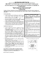
De-Aeration Function
•
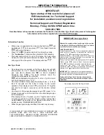
When power is supplied to the boiler for the first time
will
be displayed. If
is shown, press
, for at least 2 seconds
will now be displayed.
•
Press
&
together and hold for at least 6 seconds.
The “
De-Aeration
” Function will be activated & “
On
” showing.
•
The boiler pump will run for up to 10 minutes. For 3-way valve
models the valve will switch between heating & hot water. This
will purge air from the system. The display will show
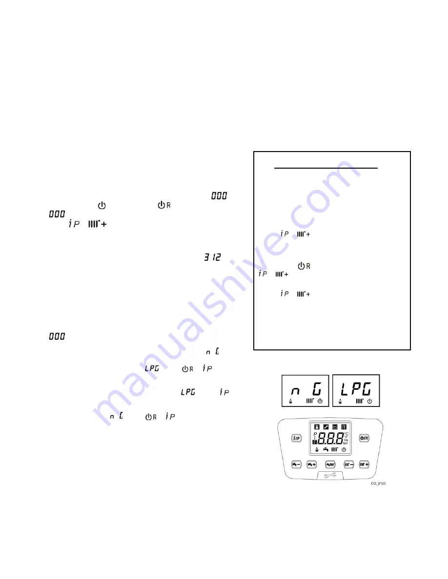
Gas Type Check
•
Once de-aeration is complete on first fire-up the boiler will light
and operates for 6 or 7 minutes to automatically check the
gas type Gas A (Natural Gas “
NG
”) or Gas E (Liquefied
Petroleum Gas “
LPG
”). The boiler software check the
combustion value against the set value.
will be displayed
alternating the
%
value
of ignition power
and the temperature value °F(°C).
•
On a Gas A (Natural Gas) supply the display shows
for at
least 10 seconds and the boiler is ready for the normal
operation. If the display shows , press
&
together
and hold for at least 4 seconds to exit the function without
saving.
•
On a Gas E (LPG) supply the display show
, press
for
at least 6 seconds to confirm that this is the intended gas type
for the installation
.
If the display shows , press
&
together and hold for
at least 4 seconds to exit the function without saving then
modify
P02=01
as described in the Manual Instructions for the
Installer section “PARAMETERS SETTING”.
•
While the gas type is being identified, the boiler may be noisy.
IF THE BOILER IS TO BE OPERATED ON GAS E (LP) REPLACE THE
EXISTING LABEL WITH THE GAS E LABEL SUPPLIED WITH
TH
IS INSTRUCTION
.
ASSURE FACTORY SUPPLIED CONVERSION
LABEL IS APPLIED TO PRODUCT IF CONVERTING TO LP.
IMPORTANT: Gas type Check
Ensure
the maximum heat exchange to the system
in Heating or DHW mode (DHW request) in order to
avoid the boiler shutoff for overheating.
FUNCTION INTERRUPT
If either De-aeration or Gas Check is interrupted by electrical
power failure is necessary to reactivate the function by
pressing
&
together for at least 6 seconds.
During De-aeration, if the display shows E118 (water low
pressure), open the water filling tap and repressurising the
system to the correct pressure value.
During Gas Type Check, if the display shows E133 (Ignition
Failure), press
button to Reset then press together
&
for at least 6 seconds to restart the function.
During Gas Type Check, if the boiler switch off for
overheating failure is necessary to reactivate the function by
pressing
&
together for at least 6 seconds.
IMPORTANT
: The combustion for this appliance has been
checked, adjusted and pre-set at the factory for operation on
the gas type specified on the appliance data plate.
During the Gas Type Check Function the combustion
ratio will increase for a short time while the gas type is
established.
The display shows the Gas Type Check
IMPORTANT INFORMATION
READ THIS LEAFLET BEFORE COMMISSIONING THE BOILER
IMPORTANT:
Upon
startup
of this
new
boiler
please call
ECR International, Inc. Technical Support
for
installation assistance and registration
.
Technical Support
and Product Registration
Monday
-
Friday
8AM to 6PM Eastern time.
1.800.253.7900
Described below is the procedure to activate the De-Aeration Function/Gas Type Check when power is first supplied
to the boiler and the actions required when on a Gas E (LPG) supply.
240011376 REV
C
, [0
5
/
30
/2016]
Summary of Contents for DCB-125
Page 2: ...DCC 205 ...
Page 4: ...DCB 165 ...
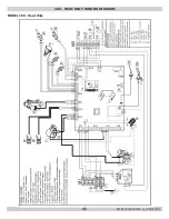
Page 65: ...61 APPENDIX A WIRING DIAGRAMS A 1 MODELS 125 Heat Only 240011947 REV B 03 31 2018 ...
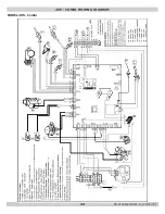
Page 66: ...62 APPENDIX A WIRING DIAGRAMS A 2 MODELS 165 Heat Only 240011947 REV B 03 31 2018 ...
Page 67: ...63 APPENDIX A WIRING DIAGRAMS A 3 MODELS 150 Combi 240011947 REV B 03 31 2018 ...
Page 68: ...64 APPENDIX A WIRING DIAGRAMS A 4 MODELS 205 Combi 240011947 REV B 03 31 2018 ...
Page 69: ...65 NOTES 240011947 REV B 03 31 2018 ...
Page 70: ...66 NOTES 240011947 REV B 03 31 2018 ...
Page 81: ...9 125 WITH ZONE CIRCULATOR PUMPS 125 with Zone Circulator Pumps PN 240011430 REV G 03 31 18 ...
Page 84: ...12 125 WITH ZONE VALVES PIPING DIAGRAM 125 with Zone Valves PN 240011430 REV G 03 31 18 ...
Page 90: ...18 165 with Zone Valves 165 WITH ZONE VALVES PIPING DIAGRAM PN 240011430 REV G 03 31 18 ...
Page 94: ...22 150 205 WITH ZONE PUMPS WIRING DIAGRAM 150 205 With Zone Pumps PN 240011430 REV G 03 31 18 ...
Page 102: ...30 MODEL 125 Heat Only 125 HEAT ONLY WIRING DIAGRAM PN 240011430 REV G 03 31 18 ...
Page 103: ...31 MODEL 165 Heat Only 165 HEAT ONLY WIRING DIAGRAM PN 240011430 REV G 03 31 18 ...
Page 104: ...32 MODEL 150 Combi 150 COMBI WIRING DIAGRAM PN 240011430 REV G 03 31 18 ...
Page 105: ...33 MODEL 205 Combi 205 COMBI WIRING DIAGRAM PN 240011430 REV G 03 31 18 ...
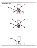
Page 110: ...38 Low Water Cutoff Detail LOW WATER CUTOFF NO NO YES PN 240011430 REV G 03 31 18 ...
Page 111: ...39 NOTES PN 240011430 REV G 03 31 18 ...
Page 112: ......
Page 115: ......
Page 116: ......

