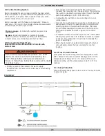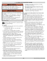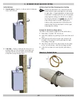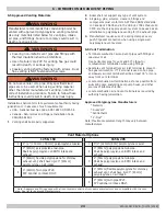
25
6 - COMBUSTION AIR AND VENT PIPING
WT
(X)
(X)
Wall Thickness
WT = Wall Thickness
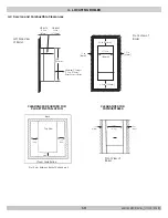
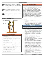
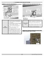
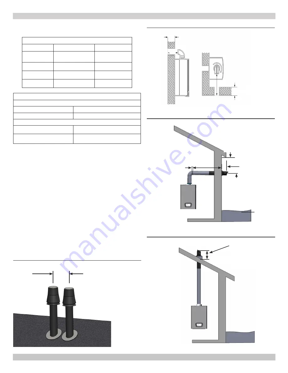
FIGURE 6-5 Side Wall Coaxial Venting
FIGURE 6-6 Roof Mount Coaxial Venting
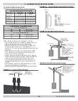
FIGURE 6-4 - Coaxial Venting Horizontal or Vertical
2” (50 mm)
X
Min. 8" (181 mm)
Max. 14" (356 mm)
Maintain 12"(305mm)
US (18"(457mm)
Canada) clearance
above highest
anticipated snow level
24" (610mm) above
roof or ground
Ground
Anticipated
Snow Line
Maintain 12"(305mm)
US (18"(457mm)
Canada) clearance
above highest
anticipated snow level
24" (610mm) above
roof or ground
Anticipated
Snow Line
18" Vertical
Clearance to
ventilated soffit
6.7 Coaxial Venting Instructions
Maximum equivalent flue lengths for Coaxial venting are:
Coaxial Pipe Maximum Vent Lengths
Boiler Size
125/150
165/205
Vent Size
4"/2"
[100mm/60mm]
5"/3"
[128mm/80mm]
Natalini
32.80 ft [10m]
32.80 ft [10m]
DuraVent
®
27.88 ft [8.5m]
32.80 ft [10m]
Centrotherm
24.60 ft [7.5m]
32.80 ft [10m]
Coaxial Elbows - Equivalent length
4"/2" [100mm/60mm]
45°
1.64 ft. [0.5m]
90°
3.28 ft. [1.0m]
5” / 3” [128mm/80mm]
45°
1.64 ft. [0.5m]
90°
3.28 ft. [1.0m]
NOTE: Coaxial venting can run horizontal or vertical.
•
Connect flue elbow to top of boiler and adjust direction of
elbow to desired orientation (rear, right or left).
• Measure distance from outside wall face to elbow, this
dimension will be known as 'X", add distance "Y" + 2"
(50mm) to "X" this is the total dimension of the vents. See
Figure 6.4.
• Mark dimension from above on outer aluminum intake
vent. Measure length of waste material, and transfer
dimension to inner grey flue pipe.
•
Remove waste from both vents (flue and air). Verify cut
ends are square and free from burrs. Insert flue back into
intake air vent and pass them through hole in wall.
• Check all measurements before cutting. Clearance to
combustible materials is zero when using coaxial vent
system.
• After installing venting use calibrated analyzer to verify
there is no recirculation of combustion.
• Ensure termination is positioned with slots at the bottom.
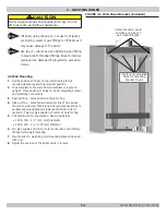
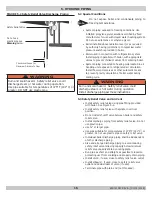
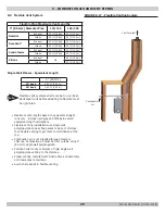
FIGURE 6-3 - Coaxial Vertical Exhaust
12" (305mm) Minimum
Separation
Manufacturer
Recommends
Greater Separation
240011947 REV B, [03/31/2018]
Summary of Contents for DCB-125
Page 2: ...DCC 205 ...
Page 4: ...DCB 165 ...
Page 65: ...61 APPENDIX A WIRING DIAGRAMS A 1 MODELS 125 Heat Only 240011947 REV B 03 31 2018 ...
Page 66: ...62 APPENDIX A WIRING DIAGRAMS A 2 MODELS 165 Heat Only 240011947 REV B 03 31 2018 ...
Page 67: ...63 APPENDIX A WIRING DIAGRAMS A 3 MODELS 150 Combi 240011947 REV B 03 31 2018 ...
Page 68: ...64 APPENDIX A WIRING DIAGRAMS A 4 MODELS 205 Combi 240011947 REV B 03 31 2018 ...
Page 69: ...65 NOTES 240011947 REV B 03 31 2018 ...
Page 70: ...66 NOTES 240011947 REV B 03 31 2018 ...
Page 81: ...9 125 WITH ZONE CIRCULATOR PUMPS 125 with Zone Circulator Pumps PN 240011430 REV G 03 31 18 ...
Page 84: ...12 125 WITH ZONE VALVES PIPING DIAGRAM 125 with Zone Valves PN 240011430 REV G 03 31 18 ...
Page 90: ...18 165 with Zone Valves 165 WITH ZONE VALVES PIPING DIAGRAM PN 240011430 REV G 03 31 18 ...
Page 94: ...22 150 205 WITH ZONE PUMPS WIRING DIAGRAM 150 205 With Zone Pumps PN 240011430 REV G 03 31 18 ...
Page 102: ...30 MODEL 125 Heat Only 125 HEAT ONLY WIRING DIAGRAM PN 240011430 REV G 03 31 18 ...
Page 103: ...31 MODEL 165 Heat Only 165 HEAT ONLY WIRING DIAGRAM PN 240011430 REV G 03 31 18 ...
Page 104: ...32 MODEL 150 Combi 150 COMBI WIRING DIAGRAM PN 240011430 REV G 03 31 18 ...
Page 105: ...33 MODEL 205 Combi 205 COMBI WIRING DIAGRAM PN 240011430 REV G 03 31 18 ...
Page 110: ...38 Low Water Cutoff Detail LOW WATER CUTOFF NO NO YES PN 240011430 REV G 03 31 18 ...
Page 111: ...39 NOTES PN 240011430 REV G 03 31 18 ...
Page 112: ......
Page 115: ......
Page 116: ......

