29
6 - COMBUSTION AIR AND VENT PIPING
6.9 Flexible Vent System
Flexible Pipe Maximum Vent Lengths
3” [80 mm] Diameter Pipe
125/150
165/205
Natalini
Exhaust
75 ft [22.8m]
50 ft [15.2m]
Intake
50 ft [15.2m]
50 ft [15.2m]
DuraVent
®
Exhaust
82 ft [24.9m]
50 ft [15.2m]
Intake
50 ft [15.2m]
50 ft [15.2m]
Centrotherm
Exhaust
52 ft [15.8m]
50 ft [15.2m]
Intake
50 ft [15.2m]
50 ft [15.2m]
Z-Dens
Exhaust
NA
50 ft [15.2m]
Intake
50 ft [15.2m]
Single Wall Elbows - Equivalent Length
3" [80 mm]
45° bend
0.82 ft [0.25 m]
90° bend
1.64 ft [0.50 m]
• Maximum vent lengths based on equivalent straight
runs only. Include rigid pipe and fittings in overall
equivalent length calculations.
• Flexible venting installations use single wall
polypropylene to pass flue gasses to base of chimney,
then flexible venting to get them to termination at the
top.
• Combustion air is not supplied through masonry
chimney. Combustion air must be from outside using 3"
[80 mm] single wall polypropylene.
• Position boiler to use minimum of rigid single wall
polypropylene venting to the chimney.
• Follow venting manufacturer's instructions on assembly
and clearances to maintain.
•
Avoid sharp bends in flexible venting.
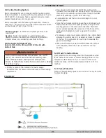
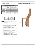
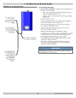
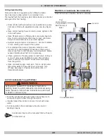
FIGURE 6-17 - Flexible Venting System
Combustion
Air
Vent Terminal
Flexible Vent
Note
Flexible vent systems shall only be run vertical.
Horizontal runs before adapting to flexible must
be rigid pipe.
Rigid Vent
240011947 REV B, [03/31/2018]
Summary of Contents for DCB-125
Page 2: ...DCC 205 ...
Page 4: ...DCB 165 ...
Page 65: ...61 APPENDIX A WIRING DIAGRAMS A 1 MODELS 125 Heat Only 240011947 REV B 03 31 2018 ...
Page 66: ...62 APPENDIX A WIRING DIAGRAMS A 2 MODELS 165 Heat Only 240011947 REV B 03 31 2018 ...
Page 67: ...63 APPENDIX A WIRING DIAGRAMS A 3 MODELS 150 Combi 240011947 REV B 03 31 2018 ...
Page 68: ...64 APPENDIX A WIRING DIAGRAMS A 4 MODELS 205 Combi 240011947 REV B 03 31 2018 ...
Page 69: ...65 NOTES 240011947 REV B 03 31 2018 ...
Page 70: ...66 NOTES 240011947 REV B 03 31 2018 ...
Page 81: ...9 125 WITH ZONE CIRCULATOR PUMPS 125 with Zone Circulator Pumps PN 240011430 REV G 03 31 18 ...
Page 84: ...12 125 WITH ZONE VALVES PIPING DIAGRAM 125 with Zone Valves PN 240011430 REV G 03 31 18 ...
Page 90: ...18 165 with Zone Valves 165 WITH ZONE VALVES PIPING DIAGRAM PN 240011430 REV G 03 31 18 ...
Page 94: ...22 150 205 WITH ZONE PUMPS WIRING DIAGRAM 150 205 With Zone Pumps PN 240011430 REV G 03 31 18 ...
Page 102: ...30 MODEL 125 Heat Only 125 HEAT ONLY WIRING DIAGRAM PN 240011430 REV G 03 31 18 ...
Page 103: ...31 MODEL 165 Heat Only 165 HEAT ONLY WIRING DIAGRAM PN 240011430 REV G 03 31 18 ...
Page 104: ...32 MODEL 150 Combi 150 COMBI WIRING DIAGRAM PN 240011430 REV G 03 31 18 ...
Page 105: ...33 MODEL 205 Combi 205 COMBI WIRING DIAGRAM PN 240011430 REV G 03 31 18 ...
Page 110: ...38 Low Water Cutoff Detail LOW WATER CUTOFF NO NO YES PN 240011430 REV G 03 31 18 ...
Page 111: ...39 NOTES PN 240011430 REV G 03 31 18 ...
Page 112: ......
Page 115: ......
Page 116: ......

