35
8 - ELECTRICAL CONNECTIONS
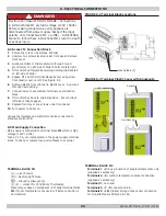
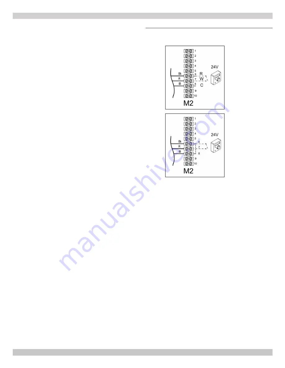
A. Connect 24V Room Thermostat
• turn power off to boiler;
• access terminal block
M2
;
• connect 24V room thermostat to terminals
6(R)-
7(W)-8(C)
; Do not apply dry volt between 2
terminals. Dry contact only.
• turn boiler power on;
• verify room thermostat operates per thermostat
manufacturer instructions.
NOTE:
maximum load allowed is 10 mA
B. Connect 24V Heat Anticipator Room Thermostat
• turn power off to boiler;
• access terminal block
M2
;
• connect wires of 24V Heat anticipator room thermostat
to terminals
6-7
;
• connect bridge between terminals
6-8
;
• turn boiler power on;
• verify 24 V Heat anticipator room thermostat operates
per thermostat manufacturer instructions.
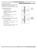
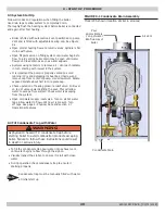
FIGURE 8-4 Thermostat Connections
8.6 Install Room Thermostat
Install room thermostat on inside wall. Do not install where it
will be influenced by drafts, hot or cold water pipes, lighting
fixtures, television, sun rays or near a fireplace.
Dry contact only - do not apply 24 volts between 6 and 7.
A
B
24V Room
Thermostat
24V Heat
Anticipator Room
Thermostat
240011947 REV B, [03/31/2018]
Summary of Contents for DCB-125
Page 2: ...DCC 205 ...
Page 4: ...DCB 165 ...
Page 65: ...61 APPENDIX A WIRING DIAGRAMS A 1 MODELS 125 Heat Only 240011947 REV B 03 31 2018 ...
Page 66: ...62 APPENDIX A WIRING DIAGRAMS A 2 MODELS 165 Heat Only 240011947 REV B 03 31 2018 ...
Page 67: ...63 APPENDIX A WIRING DIAGRAMS A 3 MODELS 150 Combi 240011947 REV B 03 31 2018 ...
Page 68: ...64 APPENDIX A WIRING DIAGRAMS A 4 MODELS 205 Combi 240011947 REV B 03 31 2018 ...
Page 69: ...65 NOTES 240011947 REV B 03 31 2018 ...
Page 70: ...66 NOTES 240011947 REV B 03 31 2018 ...
Page 81: ...9 125 WITH ZONE CIRCULATOR PUMPS 125 with Zone Circulator Pumps PN 240011430 REV G 03 31 18 ...
Page 84: ...12 125 WITH ZONE VALVES PIPING DIAGRAM 125 with Zone Valves PN 240011430 REV G 03 31 18 ...
Page 90: ...18 165 with Zone Valves 165 WITH ZONE VALVES PIPING DIAGRAM PN 240011430 REV G 03 31 18 ...
Page 94: ...22 150 205 WITH ZONE PUMPS WIRING DIAGRAM 150 205 With Zone Pumps PN 240011430 REV G 03 31 18 ...
Page 102: ...30 MODEL 125 Heat Only 125 HEAT ONLY WIRING DIAGRAM PN 240011430 REV G 03 31 18 ...
Page 103: ...31 MODEL 165 Heat Only 165 HEAT ONLY WIRING DIAGRAM PN 240011430 REV G 03 31 18 ...
Page 104: ...32 MODEL 150 Combi 150 COMBI WIRING DIAGRAM PN 240011430 REV G 03 31 18 ...
Page 105: ...33 MODEL 205 Combi 205 COMBI WIRING DIAGRAM PN 240011430 REV G 03 31 18 ...
Page 110: ...38 Low Water Cutoff Detail LOW WATER CUTOFF NO NO YES PN 240011430 REV G 03 31 18 ...
Page 111: ...39 NOTES PN 240011430 REV G 03 31 18 ...
Page 112: ......
Page 115: ......
Page 116: ......

