42
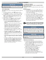
NOTICE
All connections shall be made and water added before
performing this function.
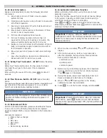
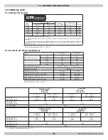
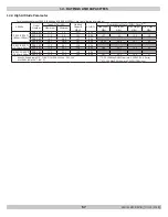
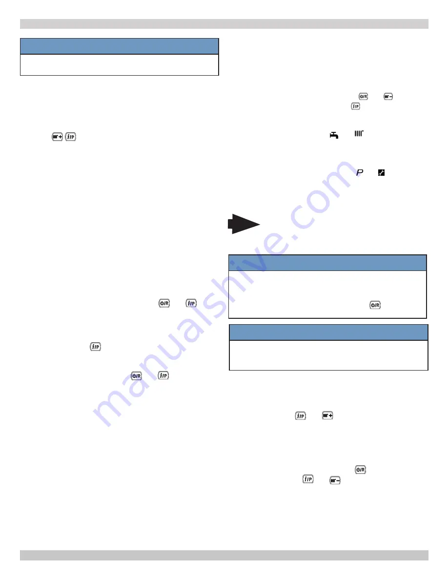
9.6 Commissioning
When lighting the boiler for the first time perform the following
procedure:
1.
Turn power to boiler on. Code
"000"
appears on the
display. Appliance is ready for "commissioning" procedure.
2.
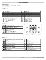
Press
at the same time. Hold for 6 seconds. "
On
"
appears on the display for 2 seconds followed by code
"
312
" indicating "
de-aeration
" function is active. This
function lasts 10 minutes.
3.
Boiler will turn on after dearation function is complete.
Display will show code "
000
" alternating with
%
of
ignition power and temperature value (°F / °C).
• During this
gas recognition function
phase which
lasts about 7 minutes, type of gas being used is
analyzed.
• During this function, assure maximum heat exchange
to heating or DHW system (domestic hot water
demand) by having all heating zones open or all
domestic hot water taps open, in order to prevent
boiler from switching off due to overheating.
• If boiler operates on Gas A (Natural Gas), display
shows
NG
(Natural Gas) for about 10 seconds. Boiler
is now ready for normal operation.
• If display shows
LPG
(Gas E), press
and
together and hold down for at least 4 seconds to exit
without changing factory setting. Boiler will stay set to
Natural Gas.
• If boiler operates on Gas E (LPG) display shows
LPG
(Gas E). Press
for at least 6 seconds to confirm gas
used.
• If display shows
NG
(Gas A) and does not recognize
the type of gas used, press
and
together and
hold down for at least 4 seconds to exit the function.
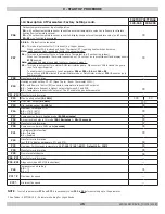
Then change parameter
P02=01
as described in
section 9.12 Parameter
Settings
of boiler Installation,
Operation and Maintenance Manual.
9 - START UP PROCEDURE
NOTICE
During initial ignition, burner may not ignite. This may
cause boiler to shut down until any air in gas pipes is
vented. Repeat ignition procedure until gas reaches the
burner. To reset boiler operation, press
for at least
2 seconds.
NOTICE
First ignitions immediately after installation, system will
implement a self-learning procedure to reach correct
ignition level.
IMPORTANT INFORMATION
A. If venting or gas recognition function is interrupted
by power blackout, start function again when power is
restored. Press
and
together and hold at same
time for at least 6 seconds.
B. If display shows fault
E118
(low pressure in hydraulic
circuit) during venting function, open filling tap on
appliance and restore correct pressure.
C. If gas recognition function is interrupted due
to fault (e.g.:
E133
no gas) press
to
reset. Then press
and
(for at least
6 seconds) to restart the function again.
If gas recognition function is interrupted due to
overheating, restart function by pressing and holding
down together for at least 6 seconds.
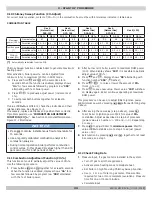
9.7 Calibration Function:
Boiler must be in stand by mode (no requests) before
initiating the function.
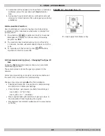
The function consists of an automatic sequence and a manual
sequence.
Automatic Sequence
a. Press together for 6 seconds the and buttons
and then within 3 seconds the
button. After 6
seconds it is possible hear a 'click' of the gas valve
and see '
On
' on the display;
b. The function is active if and blink together;
c. After ignition (also more than one attempt) the boiler
works at maximum power for at least 1 minute, then
at the ignition power, and at the end at minimum
power. When the display shows and
icons it
means the value of the curve has been stored. During
the function the display shows the power level and
flow temperature alternately.
Note
Boiler must not shutoff during calibration.
Open all heating zones in heating or DHW
mode to ensure boiler does not shutoff.
240011947 REV B, [03/31/2018]
Summary of Contents for DCB-125
Page 2: ...DCC 205 ...
Page 4: ...DCB 165 ...
Page 65: ...61 APPENDIX A WIRING DIAGRAMS A 1 MODELS 125 Heat Only 240011947 REV B 03 31 2018 ...
Page 66: ...62 APPENDIX A WIRING DIAGRAMS A 2 MODELS 165 Heat Only 240011947 REV B 03 31 2018 ...
Page 67: ...63 APPENDIX A WIRING DIAGRAMS A 3 MODELS 150 Combi 240011947 REV B 03 31 2018 ...
Page 68: ...64 APPENDIX A WIRING DIAGRAMS A 4 MODELS 205 Combi 240011947 REV B 03 31 2018 ...
Page 69: ...65 NOTES 240011947 REV B 03 31 2018 ...
Page 70: ...66 NOTES 240011947 REV B 03 31 2018 ...
Page 81: ...9 125 WITH ZONE CIRCULATOR PUMPS 125 with Zone Circulator Pumps PN 240011430 REV G 03 31 18 ...
Page 84: ...12 125 WITH ZONE VALVES PIPING DIAGRAM 125 with Zone Valves PN 240011430 REV G 03 31 18 ...
Page 90: ...18 165 with Zone Valves 165 WITH ZONE VALVES PIPING DIAGRAM PN 240011430 REV G 03 31 18 ...
Page 94: ...22 150 205 WITH ZONE PUMPS WIRING DIAGRAM 150 205 With Zone Pumps PN 240011430 REV G 03 31 18 ...
Page 102: ...30 MODEL 125 Heat Only 125 HEAT ONLY WIRING DIAGRAM PN 240011430 REV G 03 31 18 ...
Page 103: ...31 MODEL 165 Heat Only 165 HEAT ONLY WIRING DIAGRAM PN 240011430 REV G 03 31 18 ...
Page 104: ...32 MODEL 150 Combi 150 COMBI WIRING DIAGRAM PN 240011430 REV G 03 31 18 ...
Page 105: ...33 MODEL 205 Combi 205 COMBI WIRING DIAGRAM PN 240011430 REV G 03 31 18 ...
Page 110: ...38 Low Water Cutoff Detail LOW WATER CUTOFF NO NO YES PN 240011430 REV G 03 31 18 ...
Page 111: ...39 NOTES PN 240011430 REV G 03 31 18 ...
Page 112: ......
Page 115: ......
Page 116: ......

