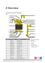
5.3 BUMP STOP REMOVAL AND FITTING OF UPPER BRACKET
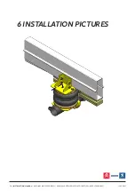
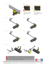
1. Remove the bump stop by prizing it away from its mount— Figures 1 and 2. One of the two holes vacated
by removal of the bump stop will be used for attachment of the upper bracket.
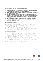
2. Choose the correct holes to attach the small flange bracket. Use the four M8 x 20 bolts, eight washers and
four self locking nuts—Figures 3 and 4.
3. Attach the upper bracket to the chassis, such that the lower flange of the bracket presses against the
lower part of the chassis rail—Figures 3 to 5. It is likely that you will need to loosen the two bolts that hold
together the two slidable parts of the bracket and then re-tighten them once the bracket is in place
against the chassis.
4. The upper bracket has a nut welded to it to which the small L-shaped bracket is attached. Attach this
small bracket such that its ‘lip’ part is over the seam of the chassis, use the M8 x 20 bolt, washer and
spring washer to secure —Figures 6 and 7.
5.4 FITTING OF LOWER BRACKET
The lower bracket is attached directly beneath the upper bracket, making use of two flanges built on to the
axle with which the bump stop would have been in contact when the vehicle suspension was in its
compressed (‘bump’) position—Figure 8.
1. Place the lower bracket in position against the axle—Figures 9 and 10
2. Secure the lower bracket to the axle flanges using the two small U-shaped brackets, by using four M6 x
20 bolts, eight washers and four self locking nuts—Figures 11 and 12
5.5 FITTING OF AIR BELLOW
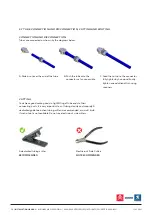
1. See Section 5.7 - “Tube Connection and Disconnection, Cutting and Routing” : Connect a tube to the
bellow by pushing the tube into the air inlet port on the underside of the spring and then hand-rotating
the tube by one screw turn. Use black tubing for the left-hand bellow and blue for the right-hand bellow.
Feed the tube through the hole in the upper bracket.
2. Place the bellow into position between the upper and lower brackets—Figures 14 and 15
3. Attach the bellow to the upper bracket using two M8 x 16mm bolts and two disc spring washers—Figure
16. Do not fully tighten the bolts at this stage because the bellow may require alignment once inflated
(Section 5.9).
4. Attach the bellow to the lower bracket using two M8 x 16mm bolts and two disc spring washers—Figure 16.
Do not fully tighten the bolts at this stage because the bellow may require alignment once inflated
(Section 5.9).
9 | INSTALLATION MANUAL |
AUXILIARY AIR SUSPENSION | X280/X290:
CITROËN C25, FIAT DUCATO, PEUGEOT J5 (1984-1993)
JULY 2021


