APT3500 Smart Pressure Transmitter
Operation Manual M3500-EO1G
13 DUON System Co., Ltd.
2.9 Insulation Resistance Test and Dielectric Strength Test
Since the transmitter has undergone insulation resistance and dielectric strength tests at the factory
before shipment, normally these tests are not required. However, if required, observe the following
precautions in the test procedures.
(1) Do not perform such tests more frequently than is absolutely necessary. Even test voltages that
do not cause visible damage to the insulation may degrade the insulation and reduce safety margins.
(2) Never apply a voltage exceeding 500 Vdc (100 Vdc with an internal lightening protector) for
the insulation resistance test, nor a voltage exceeding 500V AC (100V AC with an internal lighting
protector) for the dielectric strength test.
(3) Before conducting these tests, disconnect all signal lines from the transmitter terminals.
Perform the tests in the following procedure.
(4) Insulation Resistance test
(a) Short-circuit the + and - SUPPLY terminals in the terminal box.
(b) Turn OFF the insulation tester. Then connect the insulation tester plus (+) lead wire to the
shorted SUPPLY terminals and the minus (-) lead wire to the grounding terminal.
(c) Turn ON the insulation tester power and measure the insulation resistance. The voltage
should be applied short as possible to verify that insulation resistance is at least 20M
Ω
.
(d) After completing the test and being very careful not to touch exposed conductors disconnect
the insulation tester and connect a 100k
Ω
resister between the grounding terminal and the short-
circuiting SUPPLY terminals. Leave this resistor connected at least three second to discharge any static
potential. Do not touch the terminal while it is discharging.
(5) Dielectric Strength Test
(a) Short-circuit the + and - SUPPLY terminals in the terminal box.
(b) Turn OFF the dielectric strength tester. Then connect the tester between the shorted SUPPLY
terminal and the grounding terminal. Be sure to connect the grounding lead of the dielectric strength
tester to the ground terminal.
▲
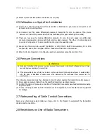
Warning
◈
Although the transmitter has been designed to resist high frequency electrical noise, if a radio transeiver is
used near the transmitter of its external wiring, the transmitter may be affected by high frequency noise
pickup. To test for such effects, bring the transceiver in use slowly from a distance of several meters from
the transmitter, and observe the measurement loop for noise effects. Thereafter, always use the
transceiver outside the area affected by noise.


