background image

APT3500 Smart Pressure Transmitter


Operation Manual   M3500-EO1G


58                           DUON System Co., Ltd.  

transmitter and configure them without changing the slope of characterization curve but Full trim 

change the slop of characterization curve after configuration. 


Step for Full trimming.   

(1) Set up stable pressure at 0 % of what user wants to the device during stabilization time, and 

then input the low trim value on 0 %.   

(2) Set up stable pressure at 100% of what user wants to the device during stabilization time, and 
then input the high trim value on 100%. 


5.9.2  DA (Digital to Analog) Trim   

 
When the D/A trim convert sensor input signal to 4~20mA output, this ouput value scale 

minuteness. Cyclic you recommend to scale analog output for maintain scale. 

This function can manage the error about analog conversion if digital value for loop current output.   


Summary of Contents for APT3500

Page 1: ... Manual M3500 E01A Information on this manual can be changed without an advance notice APT3500 Smart Pressure Transmitter Operation Manual DUON SYSTEM CO LTD Autrol DUON SYSTEM Co Ltd http www autrol com AUTROL Series Operation Manual M3500 E01A ...

Page 2: ...APT3500 Smart Pressure Transmitter Operation Manual M3500 E01A ii Duon System Co Ltd ...

Page 3: ...so that general user can help to install and operate APT3500 Smart Pressure Transmitter efficiently Before handling APT3500 transmitter all users have to be fully aware of it Information on this manual can be changed Without an advance notice DUON SYSTEM CO Ltd 60 31 Gasan dong Guemchon gu Seoul Korea Tel 82 2 860 7900 ...

Page 4: ...Transceiver 2 9 Insulation Resistance Test and Dielectric Strength Test 2 10 Installation of Explosion Protected Type Transmitters 2 11 EMC Conformity Standards Chapter 3 Transmitter Functions 3 1 Overview 3 2 Safety Messages 3 3 Warning 3 4 Fail Mode Alarm 3 5 EEProm Write Enable and Disable Mode Switch 3 6 Configuration of Alarm and Security Jumper Procedures 3 7 Configuration of Zero and Span P...

Page 5: ...erview 5 2 Safety Messages 5 3 Configuration Data Review 5 4 Check Output 5 5 Basic Setup 5 6 Detail Setup 5 7 Configuration of Information Variable 5 8 Configuration of Breakdown Diagnostics Function 5 9 Calibration Chapter 6 Maintenance 6 1 Overview 6 2 Safety Messages 6 3 Hardware Diagnosis 6 4 Hardware Maintenance ...

Page 6: ...rt Pressure Transmitter Operation Manual M3500 EO1G 4 DUON System Co Ltd Appendix I APT3500 Smart Pressure Transmitter LCD Display Code APPENDIX II PRODUCT CERTIFICATION APPENDIX III Special Condition for Safe use ...

Page 7: ...rom a functional of performance standpoint 1 1 Using This Manual The Chapters in this operating manual provide information on installing operating and maintaining devices from the AUTROL Model APT3500 Samrt Pressure Transmitter The Chapters are organized as follows Chapter 2 Handling Cautions Chapter 2 provides instructon on commissioning and operating Model APT3500 Smart Pressure Transmitters Inf...

Page 8: ...Transmitter has to terminate 250 550 Ohm 1 3 Software Compatibility Autrol Smart Pressure Transmitter s software is implemented and complemented if necssary Uses of the transmitter will not be a compatibility software is contained in the host of the HHT ACONF312 or 275 375 475 HART Communicator In this case contact us for software DD Device Descriptor to be able to use with the transmitter you mus...

Page 9: ... Setting up transmitter basic information Tag Date Descriptor Message ⅹ LCD Display LCD mode set Whole LCD Display Decimal Place set Whole LCD Display LCD Engineering Mode set Eng Range Eng Unit Eng Transfer Function LCD Engineering Value Other Button Lock set Master Reset Whole Output Supported ⅹ Not Supported Supported but update required ...

Page 10: ... Ltd 1 4 Transmitter Components The components and figure of Autrol Smart Pressure Transmitter is suggested on the next page Follow the precedure described on figure 1 1 1 2 1 3 1 4 1 5 1 6 Figure 1 1 Model APT3500 Transmitter Exposed View Housing Figure 1 2 TRANSMITTER COMPONENTS ...

Page 11: ...APT3500 Smart Pressure Transmitter Operation Manual M3500 EO1G 9 DUON System Co Ltd Figure 1 3 Model APT3500 Exploded View Sensor Module D G L Figure 1 4 TRANSMITTER COMPONENTS ...

Page 12: ...tc Where vibration and impact is not severe Where non explosion area is matched on explosionproof regulations Where maintenance is very easy Engineering 6 Mechanical Considerations Where transmitter can be handled easily Be cautious not leaking the pressure Engineering 7 Electrical Considerations Connect 24 Vdc Power Supply is 12 Vdc 45 Vdc For HART communication total resistance on transmitter te...

Page 13: ...ure detector sections of the diaphragm seals so that no measured fluid remains on them In addition make sure before storing that the pressure detector and transmitter assemblies are securely mounted 2 4 Selecting the Installation Locations The transmitter is designed to withstand severe environmental conditions However to ensure stable and accurate operation for many years the following precaution...

Page 14: ...tails on this manual 5 Refer to On line Operation for configuring another parameters except Sensor Zero Trim 2 6 Pressure Connections The following precautions must be observed in order to safely operate the transmitter under pressure 1 Never apply a pressure higher than the specified maximum working pressure 2 Confirm the option of pressure connection of transmitter Necessarily use standardized a...

Page 15: ... minus lead wire to the grounding terminal c Turn ON the insulation tester power and measure the insulation resistance The voltage should be applied short as possible to verify that insulation resistance is at least 20MΩ d After completing the test and being very careful not to touch exposed conductors disconnect the insulation tester and connect a 100kΩ resister between the grounding terminal and...

Page 16: ...2 Electrical Data Supply Voltage Maximum 45 Vdc Output signal 4 20mA maximum 22mA Note3 Installation All wiring shall comply with local installation requirement The cable entry devices shall be of a certified flameproof type suitable for conditions of use Note4 Operation Wait one minute after power disconnection before opening the enclosure Take care not to generate mechanical spark when access to...

Page 17: ...es is indicated by warning symbol Refer to the following safety messages before performing an operation preceded by this symbol 3 3 Warning Warning Explosion can result in death or serious injury Do not remove the transmitter covers in explosion environments when the circuit is alive Transmitter covers must be fully engaged to meet explosionproof requirements Warning Electrical can result in death...

Page 18: ...Switch has in LCD Module and Main CPU Module and Jumper Switch Line is connected circuital In case of Not LCD Module we can use CPU Module s Fail Mode Select Jumper Switch and In case of LCD Module we can use LCD Module s Jumper Switch In this case CPU Module is selected Down side No selected we can select Down side Jumper Select Switch is followed in Figure 3 2 3 3 Select Fail Mode Both LCD Modul...

Page 19: ...nsmitter Operation Manual M3500 EO1G 17 DUON System Co Ltd Fail Mode Selection Jumper Switch of LCD Module Figure 3 1 Fail Mode and EEPROM Write Selection Jumper Switch Figure 3 2 Fail Mode Selection Jumper Switch of LCD Module ...

Page 20: ...mper to EN you can change configuration data in EEPROM No connected Jumper it is classified EN At the factory before shipment it is configured EN Following figure 3 3 CPU Modue DIP Switch 1 Fail Mode Selection 2 EEPROM Write Selection There are two security methods in APT3500 Following this 1 Security Jumper protect to writing configuration parameters of transmitter 2 Physical removing Zero and Sp...

Page 21: ...ditional devices Because progression of button manipulation is displayed on LCD button manipulation can be used only in products containing LCD module Opening the Name Plate cover in the housing top you can see ZERO and SPAN buttons This product uses contactless magnetic buttons which are completely separated from the Transmitter interior Hence this is suitable for the case such as flameproof envi...

Page 22: ...e 4 mA Put purposed pressure for zero over 10 seconds and push Zero Button over 5 seconds Then show Zero in LCD window After checking this message take off the finger from the button Push the button over 3 seconds after 1 second passes Then show ZE in LCD window By this message all zero configurations have finished If the works has failed show SPEr or SEtE in LCD window 3 Span Configurations Set t...

Page 23: ...APT3500 Smart Pressure Transmitter Operation Manual M3500 EO1G 21 DUON System Co Ltd Menu Tree of ZERO SPAN Button Function ...

Page 24: ... AREA in the above Figure ZERO SPAN input terminates button manioulation and returns you to the normal mode In the menu Tree if ZERO and SPAN button is pushed long the pushed button is input repeatedly After completing choice and input of each function choose SAVE and CANCEL to confirm the result of application SAVE and CANCEL are converted each time ZERO button is pushed and if you choose SAVE an...

Page 25: ...VE push SPAN button to apply the entered value and complete numerical input procedure If you push ZERO button while LCD displays SAVE CANCEL is displayed Then if you push SPAN button the entered value is cancelled How to input character value Function needs to put character value Functions of 333 Change Engineering Unit 41 Select Button Lock require latter input Letter input method is the same as ...

Page 26: ...AN button until tens place flickers When tens place flickers push ZERO button once to change the LCD display value to 10 0 Then push ZERO SPAN button When units place flickers push ZERO button 4 times to change the LCD display value to 14 0 Then until SAVE is displayed push ZERO SPAN button repeatedly If SAVE is displayed push SPAN Button to save set up value Loop Test Fix the 4 20mA Loop Current ...

Page 27: ...message on LCD Change Unit Executing the menu to put Zero Span button Moving to next menu to put Zero button when 1 TRIM message appear Moving to sub directory to put Span button when 2 SETUP message appear Executing the Change Unit function to put Span button when 21 UNIT message appear Until the desired Unit is displayed in the LCD lower part push ZERO button repeatedly If the desired Unit is di...

Page 28: ...Transfer Function for the 4 20mA output Executing the menu to put Zero Span button Moving to the next menu to put Zero button when 1 TRIM message appear Moving to the sub directory to put Span button when 2 Setup message appear Moving to the next menu to put Zero button when 21 Unit message appear Moving to the next menu to put Zero button when 22 U RNG message appear Moving to the next menu to pu...

Page 29: ... C RATE in the order If SPAN button is pushed after choosing LINEAR and ZERO Low cut mode is set up as Linear and Zero respectively If SPAN button is pushed after choosing C RATE a number is entered and set up as Cut rate If SAVE is displayed push SPAN Button to save set up value If SQRT Transfer Function is chosen output changes severely even by a small change to input in the region of low pressu...

Page 30: ...he sub directory to put Span button when 3 LCD message appear Executing the function to put Span button when 31 LCD MD message appear If LCD Mode set up Function is performed usable LCD modes are indicated in the 2nd line of LCD and indication contents are as follows Indication Content Explanation NOR_RO Normal Rotation Mode PV mA are indicated alternately NOR_PV PV Mode Only measured PV is indica...

Page 31: ...age appear When Decimal Place function excuted the type of decimal place will be appear on the secondline of LCD as below Display Explanation Max Value AUTO Target value will be displayed automatically Former Display Type 9999 5 0 None decimal place 9999 4 1 Display one decimal place 9999 9 3 2 Display two decimal place 999 99 2 3 Display three decimal place 99 999 1 4 Display four decimal place 9...

Page 32: ... to put Zero button when 31 LCD MD message appear Moving to the next menu to put Zero button when 32 DEC PL message appear Moving to the sub directory to put Span button when 33 ENG MD message appear Moving to the next menu to put Zero button when 331 EN URV message appear Executing the function to put Span button when 332 EN LRV message appear LCD displays the present set up value and the highest...

Page 33: ...button when 33 ENG MD message appear Moving to the next menu to put Zero button when 331 EN URV message appear Moving to the next menu to put Zero button when 332 EN LRV message appear Moving to the next menu to put Zero button when 333 E UNIT message appear Executing the function to put Span button when 334 E TRF message appear Until the desired Transfer Function either LINEAR or SQRT is displaye...

Page 34: ...procedure Select Button Lock Executing the menu to put Zero Span button Moving to the next menu to put Zero button when 1 TRIM message appear Moving to the next menu to put Zero button when 2 Setup message appear Moving to the next menu to put Zero button when 3 LCD message appear Moving to the sub directory to put Span button when 4 DEVICE message appear Executing the function to put Span button ...

Page 35: ...B LOCK message appear Executing the function to put Span button when 42 M RST message appear If SPAN Button is pushed after displaying of SAVE Transmitter is reset after a while Equivalent to turning on and off power Change HART Polling Address Set up Polling address for HART communication Executing the menu to put Zero Span button Moving to the next menu to put Zero button when 1 TRIM message app...

Page 36: ...APT3500 Smart Pressure Transmitter Operation Manual M3500 EO1G 34 DUON System Co Ltd Figure 3 11 HART communication topology ...

Page 37: ...Jumper of transmitter in the shop commissioning level Analog output of transmitter is 4 20 mA thus it requires Power Supply at 24V 12 V 45 Vdc and Ampere meter for measuring output current You must connect 250 550 ohm resistor in Power Loop for HART Communication and HHT or PC Configurator 1 HTT Hand Held Terminal or PC Configurator may connected at any termination point in the signal loop 2 HART ...

Page 38: ... 4 3 Warning Warning Explosion can result in death or serious injury Do not remove the transmitter covers in explosion environments when the circuit is alive Both transmitter covers must be fully engaged to meet explosionproof requirements Warning Electrical can result in death serious injury The qualification which is educated only the person whom it prepares will be able to establish the transmi...

Page 39: ...llation you have to handle upon commissioning on the bench with Hand Held Terminal Start Field Install a Jumper Switch Setup b Transmitter take up c Transmitter leads e Transmitter for Power Supply f Process Leak Check End Do you want Basic Setup a Unit Setup b Range Setup c Damping Setup d Transmitter Function Setup Verify a Pressure Support Yes No Do you satisfy Spec Maintenance Figure 4 1 Insta...

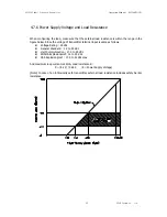
Page 40: ... field Indicator connects to TEST pin 4 6 1 Power Supply In the transmitter s power supply Input Current Voltage is currently DC voltage between DC 12 volt 45 volt and power supply s ripple is not up to 2 Loop resistance means all resistor sums in loop In case of using Intrinsic Safety Barrier same includes resistor of barrier Max Loop Resistance Ω E 12 vdc 0 022 mA Here loop resistance is prefera...

Page 41: ...er supply in terminal of the point indicated TEST It will be damage to test diode used to connecting TEST terminal 3 Seal and close the non using Conduit Connection Part for severe humidity and explosion on the terminal box of housing 4 Transmitter power is supplied to Signal Wiring So don t install near to Signal Wiring with Power Wiring or near to Power Apparatus In case of ground signal ground ...

Page 42: ... Pressure Transmitter Operation Manual M3500 EO1G 40 DUON System Co Ltd 2 2 DCS or Power Supply Local Indicator or Current Meter 1 Internal Ground Cable Entry 2 1 Figure 4 3 Picture of Terminal Board of Transmitter ...

Page 43: ...irm that the configure device has to be installed by intrinsic safety regulations Both transmitter covers must be fully engaged to meet explosion proof requirements A Loop Configuration AUTROL Series Transmitters use a two wire system for power supply 4 20mA analog signal transmission and HART digital transmission DC Power Supply is required for the transmitter loop The Transmitter and distributor...

Page 44: ...A Flameproof Type Wire cables through a flameproof packing adapter or using a flameproof metal conduit a Wiring cable through flameproof packing adapter for KOSHA flameproof type see Figure 4 4b Use only flameproof packing adapter by KOSHA Apply a non hardening sealant to the terminal box connection port and to the threads on the flameproof packing adapter for waterproofing Mounting flameproof pac...

Page 45: ...ting must be installed near the terminal box connections port for a sealed construction Apply a non hardening sealant to the threads of the terminal box connection box flexible metal conduit and deal fitting for waterproofing Figure 4 4b Typical Wiring using Flameproof Packing Adapter Figure 4 4c Typical Wiring using Flameproof Metal Conduit ...

Page 46: ...less Grounding is required below 10 Ohm for explosionproof and intrinsic safety Note In case of with Built in Lightening Protector Grounding should satisfy Special KS requirements grounding resistance 10 Ohm or less b There are ground terminal on the inside and outside of the terminal box Either of these terminals may be used c Use 600V grade PVC insulated wire for grounding ...

Page 47: ...igure below Since the voltage of transmitter terminal input is same as follows Voltage Rating 24Vdc General Standard 12 to 45 Vdc Hart Communication 17 5 to 45 Vdc KOSHA Explosionproof 12 to 45 Vdc CSA Explosionproof 17 5 to 42 Vdc max And maximum loop current is 24mA Load resistance R R E 12 0 022 E Power Supply Voltage Note In case of an intrinsically safe transmitter external load resistance in...

Page 48: ...ration Manual M3500 EO1G 46 DUON System Co Ltd 4 8 Mechanical Considerations Figure 4 3 is transmitter dimensional drawings of APT3500 A mounting example and dimensional drawings is shown in Figure 4 4 Standard Model 86 54 198 113 85 54 84 ...

Page 49: ...APT3500 Smart Pressure Transmitter Operation Manual M3500 EO1G 47 DUON System Co Ltd MP Flange High Static Pressure Model Figure 4 6 Model APT3500 Outline Dimension Drawing ...

Page 50: ...APT3500 Smart Pressure Transmitter Operation Manual M3500 EO1G 48 DUON System Co Ltd Figure 4 7 Typical Bracket Mounting ...

Page 51: ...APT3500 Smart Pressure Transmitter Operation Manual M3500 EO1G 49 DUON System Co Ltd 50 122 332 210 47 Figure 4 8 MP Option Bracket Mounting ...

Page 52: ...ing can be rotated up to 90 Terminal sides of transmitter location ease us terminal space where be able to pull out transmitter cover Circuits side of transmitter the space where there is a possibility of treating a electronic circuit the space where be able to pull out transmitter cover If LCD meter is installed it requires extra space 4 8 3 Housing Rotation and Lock Screw Figure 4 8 Lock Screw A...

Page 53: ...ct of Ambient Temperature You have to install at 20 60 4 180 operating ambient temperature range If predicted heat seems to exceed or equivalent to ambient temperature range limit you have to consider additional method to cutoff the process heat 4 9 2 Environment of toxic moisture Housing of APT 3100 can be protected to moisture or toxic material Electronic circuit side is separating from terminal...

Page 54: ...ransmitter covers in explosion environments when the circuit is alive Before connecting HHT in explosion zone confirm that the configure device has to be installed by intrinsic safety regulations Both transmitter covers must be fully engaged to meet explosion proof requirements Warning Electrical shock can result in death or serious injury If you install high voltage environment or false condition...

Page 55: ...to measure is depended Range Code of sensor This value is classified from pressure sensor module automatically 5 5 2 Set Output Units Select from the following engineering units Unit kPa kg cm2 bar psi mmH2O etc 5 5 3 Rerange Set the Zero and Span of 4 20mA analog output 5 6 Detailed Setup 5 6 1 Set Fail Mode When sensor is wrong or microprocessor of transmitter doesn t operate normally in order t...

Page 56: ...gnostic Function 5 8 1 Loop Test The Loop Test verifies the output of the transmitter the integrity of the loop and the operations of any recorders or similar devices installed loop Perform the following procedure for a loop test Connect a reference meter to the transmitter Select the Loop Test of HHT and operate the Loop Test Select output current 4mA 20mA etc If the readings match then the trans...

Page 57: ... over a specific pressure range Rerange functions provides ability to readjust the 4 20mA points sensor inputs Figure 5 2 Calibration Environment Detailed Calibration Procedure is as follows 1 In the complete vent mode without pressure approval check measured value of HHT or PC Configurator 2 After approving the pressure to be checked in general URV from the pressure source check measured value of...

Page 58: ...egarding to change is connected actually in the sensor which in order to correspond There are three waysto trim the sensor Sensor zero trim full trim and zero adjustment Sensor zero trim is a one point adjustment typically used to compensate for mounting position effects or zero shifts caused by static pressure Two point trim is a full sensor tirm in which two accurate end point pressure are appli...

Page 59: ...re approved after pressure change to be stabilized prior to execution As for Zero offset set up value for user and factory initial value are stored separately and the factory initial value can always be restored through offset factory recall function As for how to execute Zero Trim and Zero Adjutment making use of button refer to Chapter 3 7 As for how to execute Zero Trim and Zero Adjutment makin...

Page 60: ...r wants to the device during stabilization time and then input the low trim value on 0 2 Set up stable pressure at 100 of what user wants to the device during stabilization time and then input the high trim value on 100 5 9 2 DA Digital to Analog Trim When the D A trim convert sensor input signal to 4 20mA output this ouput value scale minuteness Cyclic you recommend to scale analog output for mai...

Page 61: ...itter covers in explosion environments when the circuit is alive Both transmitter covers must be fully engaged to meet explosion proof requirements Warning Electrical shock can result in death or serious injury If you install high voltage environment or false condition power line and lead will be apprered high voltages Avoid contact with the leads and terminals Warning Electrical can result in dea...

Page 62: ...r receptacles Power Supply Check the output voltage of the power supply at the transmitter terminals It should be 12 to 45 Vdc in spite of loop scale Electronics Module Connect HHT and enter the Transmitter test mode to isolate module failure Check the sensor limits to ensure calibration adjustments are within the sensor range Erratic Output Loop Wiring Check the output voltage of the power supply...

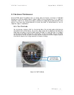
Page 63: ...ystem Co Ltd for inspection repair or replacement 6 4 1 Test Terminals The test terminal marked as TEST on the terminal block The test and negative terminals are connected to the test terminals so long as the voltage across the receptacles is kept below the diode threshold voltage no current passes through the diode To ensure that there is no leakage current through the diode while making a test r...

Page 64: ...s module The module is a non repairable unit if a malfunction occurs the entire unit must be replaced 1 Disconnect the power to the transmitter 2 Remove the cover from the electronics side of the transmitter housing Figure 6 2 Do not remove the instrument cover in explosive atmospheres when the circuit is alive Remove the LCD meter if applicable 3 Remove the two screws that anchor the electronics ...

Page 65: ...and Jumper Switch are set exactly 2 Insert electronics module in housing 3 Firstly connect the connector of sensor board with power connector Mis connection of the two connectors cause wrong output 4 20mA and effect on power of Transmitter In case of power connector sandwitched between board and housing it may cause wrong output signal and effect on power of transmitter 4 Fix electronics module wi...

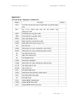
Page 66: ... ZT ERR Setting Limit 10 Error when Zero Trim TR Zero Trim Done ZR ERR Setting Limit error when executing Zero button function SP ERR Setting Limit error when executing Span button function ZR Zero button function done SP Span button function done ZA Zero Adjustment done DONE Setting Done using button R OVER Setting Limit error when executing other setting function LCD_OV Over figure values for LC...

Page 67: ...S OP Sensor Overpressure AEP RF Analog EEPROM read checksum error TS FL Temperature Sensor Error AEP WF Analog EEPROM write fail EOSC Crystal Element Defect Alarm FAVE Flash Access Violation PGM ER Program Memory CRC error PASSER Wrong password input TOO H Input number is too large TOO L Input number is too small LCD_OV The number to be displayed on LCD exceeds the display range ...

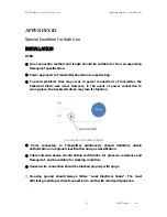
Page 68: ...u Seoul Korea 153 801 2 KOREA KOSHA Flameproof Certificate Number 12 AV2BO 0741 Ex d IIC T6 IP67 20 Tamb 60 Vdc 12 5 45Vdc 4 20mA Process Temperature Below 80 a KOREA KOSHA Flameproof Standards Notification of Protection Device Duty of Safety Certification Ministry of Employment Labor Notification No 2010 36 3 ATEX Explosion proof Certification Certificate Number xxxxxxxxxxxxxxxxx Certificate Rang...

Page 69: ... used However in the event of power connection to wrong place the backward diode may lose its function Connection of backward diode Parts connected to Transmitter additionally should definitely obtain authorization on regional classification and gas classification Cable entrance device should obtain certification for pressure resistance and flameproof and be suitable for working condition Unused w...

Page 70: ... Ground Assembly It is located at the right side of the housing front facing LCD and identified by ground symbol When impulse line is used Stopping Boxes should be directly connected to the housing wall Cable grand should obtain proper environment certification for flameproof to be used at ZONE 1 Impule line should engage at least five screw thread Sensor should engage at least seven screw thread ...

Reviews: