ATT2100 TEMPERATURE TRANSMITTER
Operation Manual M2100-REV-G
9
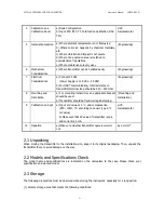
4
Calibration on a
Calibration Room
a) Basic Configuration
b) Input RTD &TC, TC Cold Juction Calibration, DAC
Trim
HHT,
Galvanometer
5 InstallationLocation
a) Where ambient temperature is not fluctuated
b) Where corrosion happens by chemical materials,
etc.
c) Where vibration and impact is not severe
d) Where non-explosion area is matched on
explosionproof regulations
e) Where maintenance is very easy
(Engineering)
6 Mechanical
Considerations
a) Where transmitter can be handled easily
(Engineering)
7 Electrical
Considerations
a) Connect 24 Vdc
(Power Supply is 11.9 Vdc – 45 Vdc)
b) For HART communication, total resistance on
transmitter terminal loop should be 250 – 550 Ohm.
(Engineering)
8 Mounting
and
Installation
a) For mounting transmitter, an appropriate bracket
should be used.
b) Transmitter should be fixed well against swing.
(Mounting and
Installation)
9
Calibration on Spot
a) Input mV value at 0
℃
, and compensation
(RTD: 100
Ω
, TC: according to sensor type 0
℃
mV value)
b) Make sure that PV value of transmitter is zero
and current is 4 mA.
HHT,
Galvanometer
10
Opeation
a) Make sure whether transmitter operates well or
not
Eye or HHT
2.1 Unpacking
When moving the transmitter to the installation site, keep it in its original packaging. Then, unpack the
transmitter there to avoid damage on the way.
2.2 Models and Specifications Check
The model name and specifications are indicated on the nameplate to the case. Please check your
specification and wanted model.
2.3 Storage
The following precautions must be observed when storing the instrument, especially for a long period.
(1) Select a storage area that meets the following conditions:

