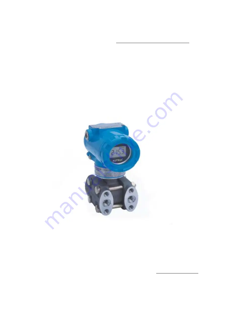
background image

Model APT3100   

Autrol Smart Pressure Transmitter

 Operating Manual


AUTROL SERIES


AUTROL

®

  Operation Manual: M3100-E01B 


DUON SYSTEM Co., Ltd.


http://www.autrol.com 


This manual can be change and revised for quality upgrade without an advance notice. 

Summary of Contents for Autrol APT3100

Page 1: ...rol Smart Pressure Transmitter Operating Manual AUTROL SERIES AUTROL Operation Manual M3100 E01B DUON SYSTEM Co Ltd http www autrol com This manual can be change and revised for quality upgrade without an advance notice ...

Page 2: ...l is made so that general user can help to install and operate APT3100 Smart Pressure Transmitter efficiently Before handling APT3100 transmitter all users have to be fully aware of it Information on this manual can be changed without an advance notice DUON SYSTEM CO LTD 60 31 Gasan dong Geumchon gu SEOUL KOREA TEL 82 2 860 7900 ...

Page 3: ...allation of Explosion Protected Type Transmitters 2 10 1 KOSHA Certification 2 10 2 KTL Certification 2 10 3 CSA Flameproof Certification 2 11 EMC Conformity Standards Chapter 3 Transmitter Functions 3 1 Overview 3 2 Safety Messages 3 3 Warning 3 4 Fail Mode Alarm 3 5 EEProm Write Enable and Disable Mode Jumper 3 6 Configuration of Alarm and Security Jumper Procedures 3 7 Configuration of Zero and...

Page 4: ...6 Detail Setup 5 7 Information Variables Setup 5 8 Diagnostics and Services 5 9 Calibration Chapter 6 Maintenance 6 1 Overview 6 2 Safety Messages 6 3 Hardware Diagnosis 6 4 Hardware Maintenance Appendix I LCD Display Code for APT3100 Smart Pressure Transmitter Appendix II 275 Hart Communicator User Guide for APT3100 Smart Pressure Transmitter Appendix III PDA User Guide for APT3100 Smart Pressure...

Page 5: ...onal of performance standpoint 1 1 Using This Manual The Chapters in this operating manual provide information on installing operating and maintaining devices from the AUTROL Model APT3100 Samrt Pressure Transmitter The Chapters are organized as follows Chapter 2 Handling Cautions This chapter consists of core information for installing APT3100 on operating place after buying it Chapter 2 provides...

Page 6: ...er has to terminate 250 550 Ohm as loop resistance by series connection But there is no additional loop resistance when transmitter is connected with analog input port or output port of control system because transmitter has self resistance 250 Ohm 1 3 Software Compatibility Autrol Smart Pressure Transmitter s software is implemented and complemented if necssary Uses of the transmitter will not be...

Page 7: ...O SMART PRESSURE TRANSMITTER AUTROL APT3100 SERIES Ex d IIC T6 IP67 OPERATION TEMP SEOUL KOREA R POWER SUPPLY OUTPUT SIGNAL 11 9 TO 45 VDC 4 TO 20 mADC HART 40 TO 85 C TAG NO R Manufactured by DUON System Co Ltd 1 4 Transmitter Components The components and figure of Autrol Smart Pressure Transmitter is suggested on the next page Follow the precedure described on figure 1 1 1 2 and 1 3 Figure 1 1 ...

Page 8: ...APT3100 Smart Pressure Transmitter Operation Manual M3100 E01B 8 DUON System Co Ltd A U T R O L A U T R O L Figure 1 2 Transmitter SENSOR MODULE D G L Exposed View and Components ...

Page 9: ...APT3100 Smart Pressure Transmitter Operation Manual M3100 E01B 9 DUON System Co Ltd A U T R O L A U T R O L Figure 1 3 Transmitter SENSOR MODULE H Exposed View and Components ...

Page 10: ...c Where vibration and impact is not severe Where non explosion area is matched on explosionproof regulations Where maintenance is very easy Engineering 6 Mechanical Considerations Where transmitter can be handled easily Be cautious not leaking the pressure Engineering 7 Electrical Considerations Connect 24 Vdc Power Supply is 11 9 Vdc 45 Vdc For HART communication total resistance on transmitter t...

Page 11: ...pack it as nearly as possible to the way it was packed when delivered from the factory 3 If storing a transmitter that has been used thoroughly clean diaphragm surfaces the pressure detector sections of the diaphragm seals so that no measured fluid remains on them In addition make sure before storing that the pressure detector and transmitter assemblies are securely mounted 2 4 Selecting Installat...

Page 12: ...manifold and to open its equalizing valve 4 Sensor Zero Trimming is to use HHT 275 calibrator PC or PDA configurator and to use Zero Span button Make sure all details on this manual 5 Refer to On line Operation for configuring another parameters except Sensor Zero Trim 2 6 Pressure Connections The following precautions must be observed in order to safely operate the transmitter under pressure 1 Ne...

Page 13: ... very careful not to touch exposed conductors disconnect the insulation tester and connect a 100kW resister between the grounding terminal and the short circuiting SUPPLY terminals Leave this resistor connected at least three second to discharge any static potential Do not touch the terminal while it is discharging 5 Dielectric Strength Test a Short circuit the and SUPPLY terminals in the terminal...

Page 14: ...nt modification or parts replacement by other than authorized representative of DUON System is prohibited and will void KOSHA Flameproof 2 10 2 KTL Certification Caution for KTL intrinsic safety type is following type Note1 Model APT3200 for potentially explosive atmosphere z Type of Protection and Marking Code Ex ia ⅡC T5 z Temperature Class T5 z Ambient Temperature 20 60 C z Process Temperature ...

Page 15: ...no use has blocked by available plugs z All screws of cable tube have to be set the 5 teeth z Method of cable connection has to be followed by Class I Division 1 in spite of its length z All cable tubes have to be sealed with 50 cm from housing z Installation in Division 2 zone does not need to be sealed z In assembly of sensor module and housing over 7 screws have to be set the teeth and be fixed...

Page 16: ...ill drive its output low down or high up based on the position of the failure mode alarm jumper See Table 3 1 for Output values Level 4 20mA Saturation 4 20mA Alarm Low Down 3 9mA 3 75mA High Up 20 8mA 21 75mA Table 3 1 Standard Alarm and Saturation Value Fail Mode Select Jumper Switch has in LCD Module and Main CPU Module and Jumper Switch Line is connected circuital In case of Not LCD Module we ...

Page 17: ...lect Fail Mode CPU Module LCD Module CPU Module Fail Down Down D D Down U Fail Up Up U or D U CPU Module Fail Mode Select Jumper Switch EEP WRITE JMM1 FAIL DIS O O O O UP O O O O EN O O O O DOWN Select EN Select Down LCD Module Fail Mode Select Jumper Switch U O O O O O O D O O O D Down selected FAIL MODE Up selected 3 5 EEProm Write Enable and Disable Mode Jumper Figure 3 2 LCD Module s Fail Mode...

Page 18: ...Span Magnetic Buttons of Transmitter you are not able to regulate Zero and Span in Local Notification If EEP Write is not connected it is classified Security Off state 3 5 1 Security Jumper EEPROM Write Protect Protect to change Configuration Parameter of transmitter to Write Protect Jumper 3 5 2 Zero and Span Magnetic Button To remove Magnetic Button you can t configure Zero and Span in Local 3 6...

Page 19: ...Set the current process value for Upperr Range Value 20 mA Put purposed pressure for zero over 10 seconds and push Span Button over 5 seconds Then show SPAn in LCD window After checking this message take off the finger from the button Push the button over 3 seconds after 1 second passes Then show SP in LCD window By this message all zero configurations have finished If the works has failed show SP...

Page 20: ...using only Sensor Zero button There are two ways for Sensor Zero Trim of APT3100 z Using Zero Span button attached on transmitter z Using HART communicator HHT etc For more information and details please refer to 275 User Guide The under guide is a Sensor Zero Trim procedure using Zero Span button 1 Loosen both bolts of Name Plate on upside transmitter and push the right end of Name Plate back a l...

Page 21: ...indow And continuously push Zero and Span button over 3 seconds again Then show Z Ad in LCD window After making sure this message 0 01 diminishes whenever Zero button is pushed and 0 01 increases whenever Span button is pushed Pushing button continuously makes speed fast or slow If you push Zero Span button over 3 seconds or do not push any button over 10 seconds Zo message shows in LCD window By ...

Page 22: ...APT3100 Smart Pressure Transmitter Operation Manual M3100 E01B 22 DUON System Co Ltd COMM TEST COMM TEST Figure 3 5 Connection the transmitter to HHT ...

Page 23: ... explosion environments when the circuit is alive Both transmitter covers must be fully engaged to meet explosionproof requirements Warning Electrical can result in death serious injury The qualification which is educated only the person whom it prepares will be able to establish the transmitter Warning Process leaks can cause death or serious injury Install and tighten before applying pressure If...

Page 24: ...ch Setup b Transmitter take up c Transmitter leads e Transmitter for Power Supply f Process Leak Check End Do you want Bench Calibration Basic Setup a Unit Setup b Range Setup c Damping Setup d Transmitter Function Setup Verify a Pressure Support Yes No Do you satisfy Spec Maintenance Figure 4 1 Installation Flow Chart ...

Page 25: ...er Supply In the transmitter s power supply Input Current Voltage is currently DC voltage between DC 11 9 volt 45 volt and power supply s ripple is not up to 2 Loop resistance means all resistor sums in loop In case of using Intrinsic Safety Barrier same includes resistor of barrier Max Loop Resistance Ω E 11 9 vdc 0 022 mA Here loop resistance is preferable at 250 550Ω 24 Vdc for the HART communi...

Page 26: ...to test diode used to connecting TEST terminal 3 Seal and close the non using Conduit Connection Part for severe humidity and explosion on the terminal box of housing 4 Transmitter power is supplied to Signal Wiring So don t install near to Signal Wiring with Power Wiring or near to Power Apparatus In case of ground signal ground the signal loop s one side and other side is not grounded Promote to...

Page 27: ...t is alive Both transmitter covers must be fully engaged to meet explosion proof requirements 4 7 4 1 Loop Configuration AUTROL Series Transmitters use a two wire system for power supply 4 20mA analog signal transmission and HART digital transmission DC Power Supply is required for the transmitter loop The Transmitter and distributor are connected as shown below 1 Non Explosionproof Flameproof Typ...

Page 28: ...ressure Transmitter Operation Manual M3100 E01B 28 DUON System Co Ltd COMM COMM TEST TEST COMM COMM TEST TEST 2 Explosionproof Type 3 Intrinsical Safety Type Figure 4 3 Connection between Transmitter and Power Supply ...

Page 29: ... using a flameproof metal conduit a Wiring cable through flameproof packing adapter for KOSHA flameproof type see Figure 4 4b Use only flameproof packing adapter by KOSHA Apply a non hardening sealant to the terminal box connection port and to the threads on the flameproof packing adapter for waterproofing Mounting flameproof packing adapter to the terminal box o Screw the flameproof packing adapt...

Page 30: ...ing for waterproofing 4 7 5 Grounding a Grounding should satisfy KS requirements grounding resistance 10 Ohm or less Grounding is required below 10 Ohm for explosionproof and intrinsic safety Note In case of with Built in Lightening Protector Grounding should satisfy Special KS requirements grounding resistance 10 Ohm or less b There are ground terminal on the inside and outside of the terminal bo...

Page 31: ...elow Since the voltage of transmitter terminal input is same as follows z General Standard 11 9 to 45 Vdc z Hart Communication 17 4 to 45 Vdc z KOSHA Explosionproof 11 9 to 45 Vdc z CSA Explosionproof 17 4 to 42 Vdc max And maximum loop current is 24mA Load resistance R R E 11 9 0 022 E Power Supply Voltage Note In case of an intrinsically safe transmitter external load resistance includes safety ...

Page 32: ...M3100 E01B 32 DUON System Co Ltd AUTROL AUTROL 4 8 Mechanical Considerations Figure 4 3 is transmitter dimensional drawings of APT3100 A mounting example and dimensional drawings is shown in Figure 4 4 Figure 4 3 Transmitter Outline Dimensional Drawings ...

Page 33: ... d e l F l a t T y p e 2 P i p e M o u n t i n g B r a c k e t V e r t i c a l M o u n t i n g T y p e H o r i z o n t a l M o u n t i n g T y p e V e r t i c a l P i p e M o u n t i n g H o r i z o n t a l P i p e M o u n t i n g H o r i z o n t a l P i p e M o u n t i n g V e r t i c a l P i p e M o u n t i n g Figure 4 4 Typical Bracket Mounting Example ...

Page 34: ...cuit the space where be able to pull out transmitter cover If LCD meter is installed it requires extra space 4 9 Environmental Considerations 4 9 1 Effect of Ambient Temperature You have to install at 20 60 4 180 operating ambient temperature range If predicted heat seems to exceed or equivalent to ambient temperature range limit you have to consider additional method to cutoff the process heat Am...

Page 35: ...xplosion zone confirm that the configure device has to be installed by intrinsic safety regulations Both transmitter covers must be fully engaged to meet explosion proof requirements Warning Electrical shock can result in death or serious injury If you install high voltage environment or false condition power line and lead will be appeared high voltages Avoid contact with the leads and terminals 5...

Page 36: ...log output 5 6 Detailed Setup 5 6 1 Set Fail Mode When sensor is wrong or microprocessor of transmitter doesn t operate normally in order to outputs current value of High or Low 5 6 2 Set Damping Time The sensor input value changes the response time of the transmitter to smooth variations in output readings caused by rapid changes in input Determine the appropriate damping setting based on the nec...

Page 37: ...ransmitter A Smart transmitter uses a microprocessor that contains information about the sensor s specific characteristics in response to pressure and temperature inputs for calculating Process Variable The trim and rerange functions also differ Reranging sets the transmitter analog output to the selected upper and lower range points and can be done with or without an applied pressure Reranging do...

Page 38: ... install high voltage environment or false condition power line and lead will be apprered high voltages Avoid contact with the leads and terminals Warning Electrical can result in death serious injury The qualification which is educated only the person whom it prepares will be able to establish the transmitter Warning Process leak can result in death serious injury Before approval pressure install...

Page 39: ...pen circuits and multiple grounds y Check for proper polarity at the signal terminals Erratic Output Electronics Module y Connect HHT and enter the Transmitter test mode to isolate an electronics mode failure Sensor Element y Connect HHT and enter the Transmitter test mode to isolate a sensor failure y Check the PV to see if it is out of range Loop Wiring y Check for adequate voltage to the transm...

Page 40: ...resistance of the test connection or meter should not exceed 10 ohms A resistance value of 30 ohms will cause an error of approximately 10 percent of reading Figure 6 1 Test Terminals 6 4 2 Disassembling the Electronics Housing The transmitter is designed with dual compartment housing one contains the electronics module and the other contains all wiring terminals and the communication receptacles ...

Page 41: ... the instrument cover in explosive atmospheres when the circuit is alive Remove the LCD meter if applicable 3 Remove the two screws that anchor the electronics module to the transmitter housing 4 Firmly grasp the electronics module and pull it straight out of the housing taking care not to damage the interconnecting pins Note2 The transmitter EEP Write Jumpers and failure mode are located on the f...

Page 42: ...UON System Co Ltd 6 4 3 Assembling the Electronics Housing Re assembling procedure is same as follows 1 Make sure that Fail mode and Jumper Switch are set exactly 2 Insert electronics module in housing 3 Fix electronics module with 3 screws 4 Close the cover of housing ...

Page 43: ...utton 9 Span Initial message in using Span button 10 2 tr Initial message of Sensor Zero Trim in using button 11 tr Good job of Sensor Zero Trim in using button 12 2ter Over 10 of Sensor Zero Trim limit in using button 13 2e Finish Zero configurations in using Zero button 14 sp Finish Span configurations in using Span button 15 Sete Fail EEPROM write in using button 16 Sper Min Max span Over in us...

Reviews: