136
v
Paper Feed Section
chap.3
440149
440150
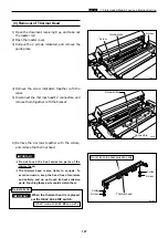
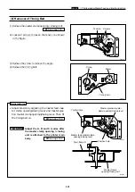
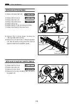
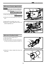
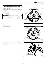
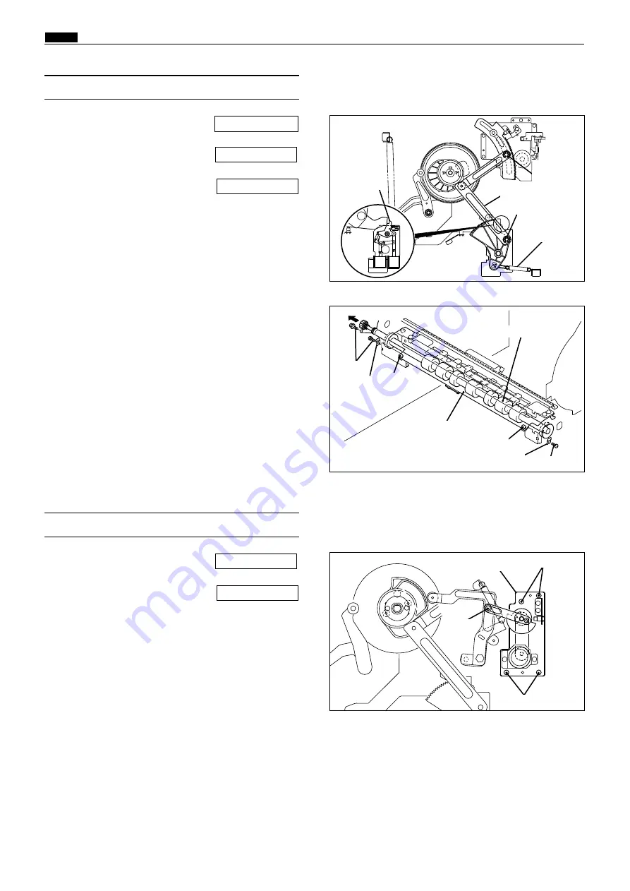
(8) Removal of Timing Roller
1) Remove the paper feed unit.
2) Remove the front cover.
3) Remove the drum unit.
4) Remove the sub-frame A.
5) Remove the spring.
6) Remove the 2 E-rings, and remove the links.
7) Remove the stopper of the cancel lever.
\
See page 137
\
See page 112
\
See page 134
Screw
Screw
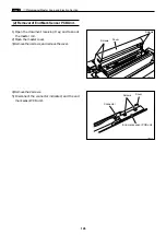
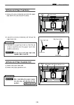
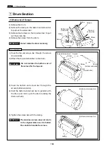
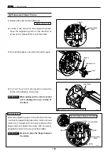
1) Remove the front cover.
2) Remove the drum unit.
3) Remove the rear cover.
4) Remove the 5 screws indicated, then remove the
long paper unit.
\
See page 114
\
See page 112
(9) Removal of Long Paper Unit(LPU) [Option]
440151
Screws
Long paper unit
Screws
8) Remove the 3 screws shown. Remove the
bearing stops and the spring.
9) Remove the 2 screws shown. Lifting the guide A
unit, and remove the timing roller from the rear
(opposite side from the operation panel).
Stopper
Timing roller
Screw
Links
E-ring
E-ring
Spring
Screws
Guide A unit
Screw
Spring
Bearing stop
Bearing stop
Summary of Contents for Duprinter DP-330
Page 9: ......
Page 11: ......
Page 18: ...c Dimensions chap 1 17 MEMO...
Page 24: ...4 8 2A 2B 2C 44000A1e b Part Names and Their Functions chap 1 23...
Page 152: ...151 MEMO...
Page 193: ...192 MEMO...
Page 329: ...328 x Overall Wiring Layout chap 8 15 Overall Wiring Layout 2 Drive PCB 2 2...

