202
z
Troubleshooting Guide
chap.6
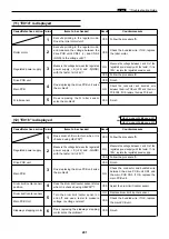
(13) "NO DRUM" is displayed
Cause/Defective section Procedures
Item to be checked
Result
Countermeasure
Drum setting.
1
YES
Finish.
Main PCB unit
2
YES
Check if drum SW is installed
in place and replace main PCB
unit.
Drum SW
3
NO
Replace drum SW.
Main PCB unit
YES
Check if drum SW is installed
in place and replace main PCB
unit.
Is trouble cleared by setting drum
again?
Does drum SW checked by HELP
mode (H-08)
*
prove to be normal?
Does drum SW checked by volt-ohm-
milliammeter prove to be normal?
HELP mode H-08
\
see p.236
*
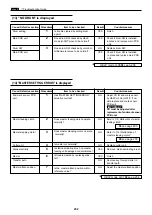
(14) "MASTER SETTING ERROR" is displayed
Cause/Defective section Procedures
Item to be checked
Result
Countermeasure
End mark sensor PCB
1
NO
Adjust VR for end mark sensor
unit
by HELP mode (H-07)
*
. If un-
able,replace end mark sensor
PCB unit.
VR must be adjusted after
replacement of end mark sensor
PCB unit.
Master feeding clutch
2
NO
Refer to “(15) Malfunction of master
feeding clutch”.
Master stepping motor
3
NO
Refer to “(16) Malfunction of
master stepping motor”.
Cutter unit
4
NO
Replace cutter unit.
Static electricity
5
YES
Remove static-eliminating brush.
Master
6
YES
Finish.
Transfer path
NO
Remove any foreign matter in
transfer path.
Master attach position
7
NO
Adjust the master attach position.
IMPORTANT:
Has “MASTER SETTING ERROR”
actually occurred?
Does master feeding clutch operate
normally?
Does master stepping motor operate
normally?
Is master cut normally?
Is static-eliminating brush on master
feeding unit damaged or deteriorated?
Is trouble cleared by replacing mas-
ter?
Is the master attach position within
reference value?
HELP mode H-07
\
see p.234
*
\
see page 203
\
see page 203
Summary of Contents for Duprinter DP-330
Page 9: ......
Page 11: ......
Page 18: ...c Dimensions chap 1 17 MEMO...
Page 24: ...4 8 2A 2B 2C 44000A1e b Part Names and Their Functions chap 1 23...
Page 152: ...151 MEMO...
Page 193: ...192 MEMO...
Page 329: ...328 x Overall Wiring Layout chap 8 15 Overall Wiring Layout 2 Drive PCB 2 2...


