207
z
Troubleshooting Guide
chap.6
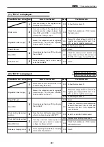
(23) "CHANGE INK" is displayed
HELP mode H-28
\
see p.257
*
Cause/Defective section Procedures
Item to be checked
Result
Countermeasure
Ink
1
NO
Replace ink pack.
Setting method of ink
2
NO
Set ink pack properly and teach
pack.
user how to set one.
Main PCB unit
3
YES
Check bundled wire and
connectors and replace main
PCB unit.
Ink detection PCB unit
4
YES
Replace Ink detection PCB unit.
5
NO
Proceed to procedure
7
.
Foreign material in ink
6
YES
Finish.
pump
Ink pump
NO
Replace ink pump.
Regulated power supply
7
NO
Replace regulated power supply.
Ink motor
8
YES
Replace ink motor
Drive PCB unit
9
YES
Finish.
Main PCB unit
NO
Check bundled wire and
connectors and replace main
PCB unit.
Is enough ink left in ink pack?
Is ink pack set properly?
Is LED on the ink detection PCB unit
lit?
Is enough ink left in drum? (Has ink
reached detection needle for the ink
detection PCB unit?)
Does ink pump operate?
Is trouble cleared by cleaning inside of
ink pump?
Does voltage between regulated
power S (+24) and -S (GND)
show 24V?
Does voltage between drive PCB unit
CN12-1 and -2 show 24V?
Is trouble cleared by replacing drive
PCB unit?
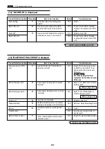
(24) "PLEASE INSERT CARD" is displayed
specification for export
Cause/Defective section Procedures
Item to be checked
Result
Countermeasure
1
NO
Proceed to procedure
5
.
How to use.
2
YES
Finish.
Keycard counter
3
NO
Connect connector properly.
connector
HELP setting.
4
NO
Set HELP mode (H-28)
*
set to“
***
1”
and HELP mode(H-70)
*
set to “
0000
”
Main PCB unit
5
YES
Finish.
Keycard counter
NO
Replace keycard counter.
Is the keycard counter connector con-
nected?
Is trouble cleared by inserting depart-
ment card as keycard?
Is the keycard counter connector con-
nected properly?
Is HELP mode(H-28)
*
set to “
***
1”
and HELP mode(H-70)
*
set to “
0000
” ?
Does voltage between main PCB unit
CN7-1 and GND about 5V?
HELP mode H-70
\
see p.297
*
Summary of Contents for Duprinter DP-330
Page 9: ......
Page 11: ......
Page 18: ...c Dimensions chap 1 17 MEMO...
Page 24: ...4 8 2A 2B 2C 44000A1e b Part Names and Their Functions chap 1 23...
Page 152: ...151 MEMO...
Page 193: ...192 MEMO...
Page 329: ...328 x Overall Wiring Layout chap 8 15 Overall Wiring Layout 2 Drive PCB 2 2...


