58
x
Platemaking / Master Feed / Ejection Section
chap.2
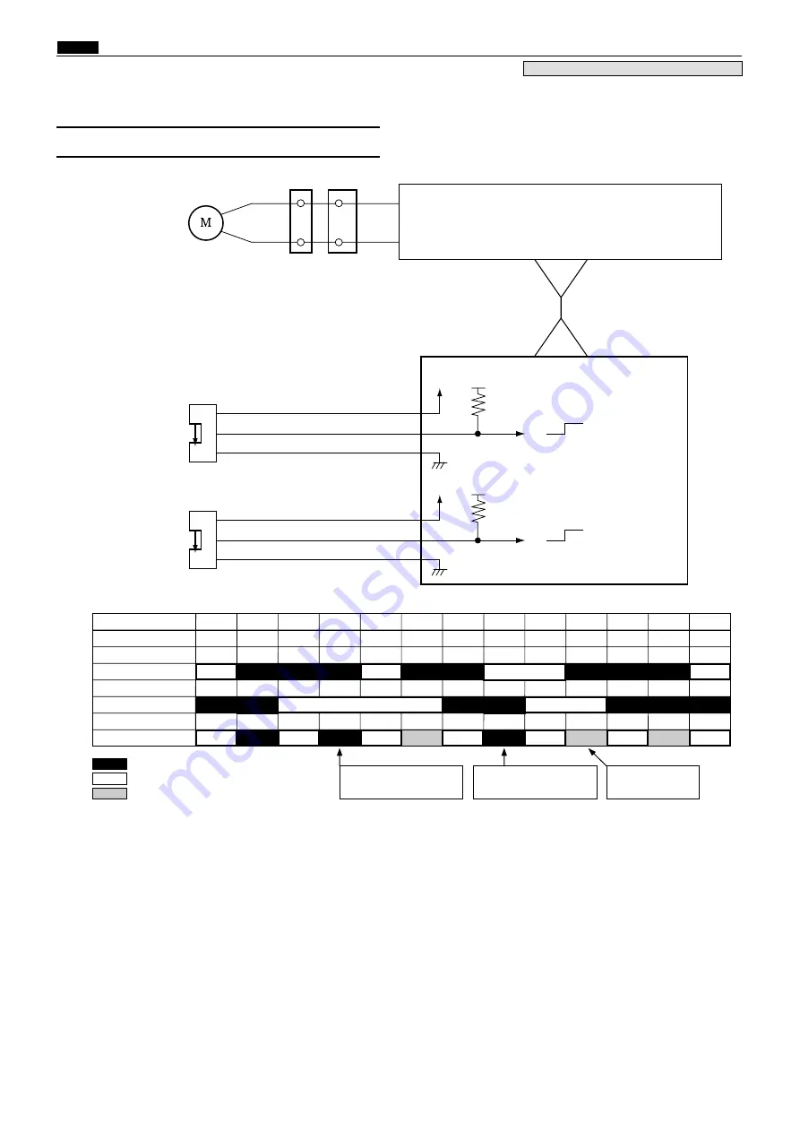
The mode is detected under the following conditions
2
A mode
When the B mode detect sensor is photointerrupted, the A / C mode detect sensor detects the edge of
photointerrupting
f
photopasing.
*With the power ON, the A mode is determined when the B mode detect sensor is in the photointerrupting
state and the A/C mode detect sensor is in the photopassing state. If not in the A mode with the power ON, the
master clamp opening / closing lever rotates to the B mode and stops. When the lever stops at the
B mode, the drum rotates with the drum rotation switch and returns to the A mode at the stop position.
2
B mode
When the A/C mode detect sensor is photointerrupted, the B mode detect sensor detects the edge of photointerrupting
/
photopassing or photopassing - photointerrupting.
2
C mode
When the B mode detect sensor is photopassing, the A/C mode detect sensor detects the edge of photointerrupting
f
photopassing.
(1) A / B / C Mode Detect Sensor
Sequence
A/C mode detect sensor
B mode detect sensor
Clamp motor
A-mode
B-mode
C-mode
B-mode
C-mode
B-mode
A-mode
Master tip end is pulled into
the master ejection box
Master tip end is fed to
the master clamp section
Master
clamp
grips
the master
tip end
: Motor normal rotation(CW), Sensor photointerruptig(ON)
: Motor stops, Sensor photopassing(OFF)
: Motor reverse rotation(CCW)
B mode detect sensor
M a i n P C B u n i t
Red
Blue
-9
1
2
3
-11
Green
-10
5V
5V
5V
0
A/C mode detect sensor
Red
Blue
CN17-3
1
2
3
-5
Orange
-4
5V
5V
5V
0
CN1-1
-32
CN9-26
-27
Clamp motor
Yellow
Orange
2
1
18
19
Drive PCB unit
-
CN3-1
-32
-
Photopassing :0V
Photointerrupting:5V
Photopassing :0V
Photointerrupting:5V
Circuit
Operation / Sequence
3. Function of Parts
440W14e
Product No.: initial lot - 020455313
440SEQ04e o
Summary of Contents for Duprinter DP-330
Page 9: ......
Page 11: ......
Page 18: ...c Dimensions chap 1 17 MEMO...
Page 24: ...4 8 2A 2B 2C 44000A1e b Part Names and Their Functions chap 1 23...
Page 152: ...151 MEMO...
Page 193: ...192 MEMO...
Page 329: ...328 x Overall Wiring Layout chap 8 15 Overall Wiring Layout 2 Drive PCB 2 2...


