93
n
Paper Ejection Section
chap.2
Description
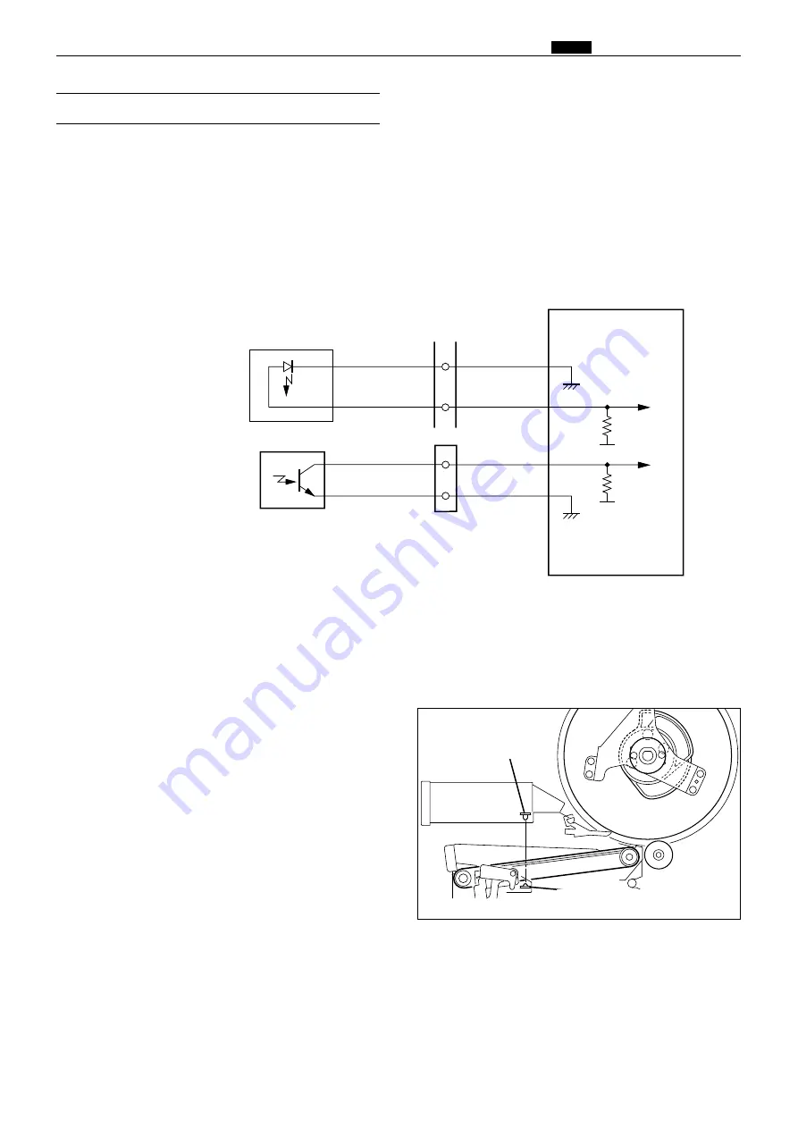
The JAM sensor photo-receiving element is installed on the paper ejection fan unit and detects whether the
paper is ejected normally. When it is detected that the paper is not ejected normally,
"PAPER JAM ON THE
EJECTION SIDE"
is displayed on the LCD panel.
Operation
The JAM photo-emitting PCB is installed in the top blow fan, and the photo-receiving PCB in the paper
ejection fan unit.
HIGH
with the optical path interrupted.
LOW
with the optical path passing.
There are two cases of interruption; interrupted by the paper and the top blow fan is open.
Blue
CN17-18
-19
-25
CN17-24
Main PCB unit
Blue
Gray
Yellow
3
5V
5V
1
2
1
Paper ejection JAM sensor
photo-emitting PCB
Paper ejection JAM sensor
photo-receiving PCB
Circuit
(3) Paper Ejection JAM Sensor
440W25e
440326
Paper ejection JAM
sensor(Photo-emitting)
Paper ejection JAM
sensor(Photo-receiving)
Summary of Contents for Duprinter DP-330
Page 9: ......
Page 11: ......
Page 18: ...c Dimensions chap 1 17 MEMO...
Page 24: ...4 8 2A 2B 2C 44000A1e b Part Names and Their Functions chap 1 23...
Page 152: ...151 MEMO...
Page 193: ...192 MEMO...
Page 329: ...328 x Overall Wiring Layout chap 8 15 Overall Wiring Layout 2 Drive PCB 2 2...


