background image


Page 7


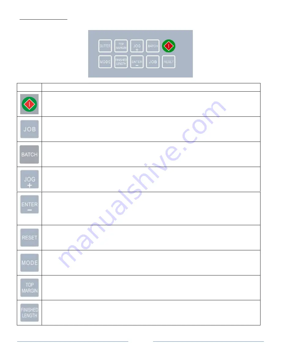
CONTROL PANEL 


Keys 

Function  


 Start and Stop the cutter 


 Change job 

 Toggle between “Normal Mode” and “Turbo Mode” (Paper Weight Setting Mode) 


 Select batch count 

 Pre-feed (Mark Reader Calibration Mode) 


 Jog forward 

 Increment settings by 0.1 mm when press. 


 Confirm job and batch count setting. 

 Decrement settings by 0.1mm when press (Mark Reader Calibration Mode). 

 Jog backward 

 Reset counter (use with “RESET” button simultaneously) 


 Save settings 

 Hold (4s) paper weight setting mode 

 Reset counter (use with “ENTER” Button simultaneously) 


 Enter program mode 

 Change paper weight 


 Set top margin 


 Set finished length 

Summary of Contents for DocuCutter CC-330

Page 1: ...Ver 20121121 A10 DocuCutterCC 330 Operational Manual Before operating the machine read this manual Follow all safety precautions ...

Page 2: ...semblies 5 Control Panel 7 Installation 8 Setting Up Procedure 9 The Job selection 11 Registration Mark Position 15 Selecting a job 15 Batch Count function 16 User Define Job 16 Turbo and normal Mode 17 Paper weight 17 Reset Counter 18 Clear Jam 18 Troubleshooting 19 Optional Slitter Cassette 19 Optional Conveyor 20 ...

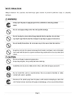
Page 3: ...e any of the covers from the machine Keep this unit and the power cord away from heaters and heater vents Excessive heat could melt the cover or power cord covering and result in a fire or an electrical shock Do not put fingers inside during operation Keep away long hair ties jewelry and loose clothing Install this unit on a level stable stand or floor with sufficient space around it Do not instal...

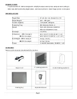
Page 4: ...y 120 sheets 300gsm Receiving Tray 250 business Card x 3 Speed Up to 240 business cards min Based on 55x90mm in A3 Accuracy 0 2 mm Dimension With Conveyor W O Conveyor 98 5 X 53 5 X 101 5CM 38 8x21 1 x 40 48 5 X 53 5 X 101 5CM 19 1 x 21 1 x 40 Net Weight With Conveyor W O Conveyor 70 8Kgs 156 lbs 61 2Kgs 135 lbs Power 110 220V Selectable 50 60Hz 1 2A ACCESSORIES Make sure all accessories provided ...

Page 5: ...Page 5 MAJOR COMPONENTS AND ASSEMBLIES 1 Power Switch 2 Control Panel 3 Extended Tray 4 Top Cover 5 Waste Compartment Door 6 Machine Stand 1 3 4 5 2 6 ...

Page 6: ...uxiliary Roller 9 Side Guide Adjustment Knob 10 Feed Tray Pressure Adjustment 11 Feed Rollers Adjustment Knob 12 Feed Rollers 13 Slitter Cassette 14 Slitting Registration Adjustment 15 Stacking Guides 7 8 12 9 13 11 10 14 15 ...

Page 7: ...de Jog forward Increment settings by 0 1 mm when press Confirm job and batch count setting Decrement settings by 0 1mm when press Mark Reader Calibration Mode Jog backward Reset counter use with RESET button simultaneously Save settings Hold 4s paper weight setting mode Reset counter use with ENTER Button simultaneously Enter program mode Change paper weight Set top margin Set finished length ...

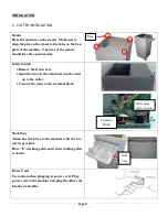
Page 8: ...move the front cover Open the door in the stand and run the wires up to the cutter Connect the wires to the terminal block Stack Tray Attach the stack tray to the machine with the two screws provided Place L stacking guide and center staking guide as shown Power Cord Use caution when plugging in power cord Plug power cord to the machine and plug the other end into the wall outlet Pins Stack Tray T...

Page 9: ...hould be flat 3 Push the feed tray down and load the paper Readjust paper guide if needed 4 Adjust tray pressure For thinner paper the number should be higher For heavier paper the number should be lower 5 Use slitter registration adjustment knob to compensate for printing registration The knob will allow 2mm of adjustment 6 Auxiliary roller is for hard to feed paper To use auxiliary roller laid t...

Page 10: ...Page 10 7 Adjust feed rollers so they are about 0 5 away from the edge on each side of the paper ...

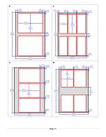
Page 11: ... 5 24 up None 0 75 19 1 mm Standard Slitter C 3 Brochure Brochure 12 X18 8 5 x 11 2 up 0 25 in 6 35 mm 0 5 12 7 mm Option Slitter A 11 in D Insert Greeting Cards 12 X18 3 5 x 8 5 6 up 0 25 in 6 35 mm 0 5 12 7 mm Standard Slitter E 4 Photo Photo 12 X18 8 x 10 2 up 1 25 in 31 75 mm 0 5 12 7 mm Option Slitter A 10 in F Insert Greeting Cards 12 X18 3 5 x 8 6 up 1 25 in 31 75 mm 0 5 12 7 mm Standard Sl...

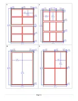
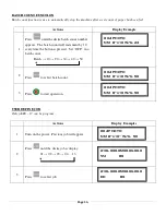
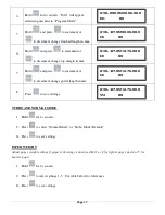
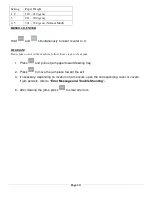
Page 12: ...Page 12 Job Layout A B C D ...

Page 13: ...Page 13 E F G H ...

Page 14: ...Page 14 I J K L ...

Page 15: ...on SELECTINGA JOB Actions Display Example 1 Turn on the power Previous job will appear 2 Press until the desire job is displayed 01 02 03 04 13 3 Press to select job 4 Press to start operation 01BUSINESS CARD NM 2 x3 5 W G 23 04 PHOTO NM 8 x10 W G 23 04 PHOTO NM 8 x10 W G 23 04 PHOTO NM 8 x10 W G 23 1st Cut Margin Center Feed ...

Page 16: ...utton is pressed Set OFF r no batch count Batch 10 20 30 40 50 2 Press to select batch count 3 Press to start operation USER DEFINE JOB Only job 8 13 can be program Actions Display Examples 1 Turn on the power Previous job will appear 2 Press until the desire job is display 01 02 03 04 13 3 Press to select job 04 PHOTO NM 8 x10 W G 23 04 PHOTO NM 8 x10 W G 50 10L000 0M00 0G00 0 NM 89 10L000 0M00 0...

Page 17: ...ss to save settings TURBO AND NORMAL MODE 1 Hold for 4 seconds 2 Press to select Normal Mode or Turbo Mode Default 3 Press to save settings PAPER WEIGHT Adjust paper weight settings if paper is skewing or miss feed Set 1 or 2 for lighter paper and 4 or 5 for heavier paper 1 Hold for 4 seconds 2 Press to select settings 1 5 Use table below for references 3 Press to save settings 10L000 0M00 0G00 0 ...

Page 18: ...case jam occurs in the machine follow these steps to clear jam 1 Press and pull out jam paper toward feeding tray 2 Press to move the jam piece toward the exit 3 If necessary depending on location of jam occurs open the corresponding cover or covers If jam persists refer to Error Message and Trouble Shooting 4 After clearing the jams press to clear all errors ...

Page 19: ...p cover Put the top cover in position check rear cover Put the rear cover in position Finish card not clean and neat Call for service Error message cannot reset Check covers and paper jam OPTIONAL SLITTER CASSETTE Optional slitters enable the CC 330 to have more range of applications Follow the step below the replace optional slitter cassette 1 Lift Top Cover 2 Remove thumbscrew by turning counter...

Page 20: ... Rollers Assembly 1 x Interface Cable 1 x Stand Support 4 x Studs 4 x Socket Cap Screws M6x12 6 x Lock Washers M6 4 X Shoulder Washers 4 x Machine Screws M4 x 12 2 x Spacer 2 x Machine Screws M5 x 35 2 X Hex Bolt M6 x 30 4 x Washers M6 2 X Hex Nuts M6 2 Thumbscrews M4 x 12 ...

Page 21: ...eyor onto the studs 4 Use 2 spacers and Machine Screws M5 x 35 to secure the conveyor on the left and right side located below the conveyor 5 Plug interface cable to conveyor and machine 6 Fasten 4 Machine Screws M4 x 12 and 4 shoulders washers the the end of the conveyor Shoulder Washers Left Side Spacer Right Side Spacer Side Cover ...

Page 22: ...Adjust roller distance depending on paper finish size for better stacking 9 Install stand support using 2 Hex Bolt M6 x 30 4 washers M6 2 Lock Washer M6 and 2 Nuts M6 and secure stand support to the stand 10 Install stand support using 5 x M5 x 10 screw and washer to secure stand support to the conveyor Conveyor Rails Thumbscrews ...

Page 23: ...Page 23 Duplo USA Corporation 3050 S Daimler St Santa Ana CA 92705 www duplousa com ...

Reviews: