198
c
HELP Mode Function and Operation Procedures
chap.7
x
Overview
The DUPRINTER's HELP modes can be broadly classified into the
following types:
◆
Modes for ROM version display / version upgrade
To display the tape cluster ROM version if the main PCB ROM,
the panel PCB ROM, FPGA and the tape cluster TAP-05 - 12 are
available
To update the main PCB ROM and the panel PCB ROM.
◆
Modes for adjustment / specification setting
These modes set the functioning of variable resistors and switches
by using the battery PCB unit's EEPROM to memorize settings
made on the operation panel. All of these adjustments and settings
are made at the factory prior to shipment of each DUPRINTER.
¡
New adjustments and appropriate settings must be made after
the battery PCB unit is replaced and after initialization setting
has been implemented (using HELP-027).
◆
Modes for function checks
These modes permit the running of function checks on:
individual motors, given series of operations, and electrical
circuits.
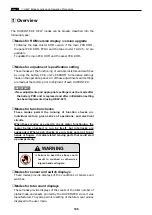
When these modes are used to check motor functioning, the
motor being checked is run by itself, but interlocks are
suspended. When such checks are run, take care not to put
hands or fingers in motor-related moving parts that could start
up unexpectedly.
IMPORTANT :
◆
Modes for sensor and switch displays
These modes provide displays of the conditions of sensors and
switches.
◆
Modes for total count displays
These modes provide displays of the counts of the total number of
plates made and sheets printed by the DUPRINTER since it was
manufactured. They also permit resetting of the total count values
displayed in the user mode.
¡
Failure to heed the above could
result in crushed or otherwise
injured hands or fingers.
WARNING
Summary of Contents for DP-S Series
Page 1: ......
Page 9: ......
Page 11: ......
Page 16: ...x Dimensions chap 1 15 R8S01001 xDimensions 622 1360 510 228 1080 710 980 688 370 mm...
Page 22: ...v Part Names and Their Functions chap 1 21 44000A1e 2A 2B 2C R8S01006a 2Detailed drawing...
Page 33: ...32 z Scanner Section chap 2 Circuit R8S02E03e...
Page 87: ...86 m Drum Section chap 2 2 Circuit R8S02E30...
Page 171: ...170 MEMO...
Page 193: ...192 MEMO...
Page 195: ...194 z Help mode List chap 7 z HELP Mode List...
Page 243: ...242 c HELP Mode Function and Operation Procedures chap 7...
Page 270: ...269 c HELP Mode Function and Operation Procedures chap 7...
Page 281: ...280 MEMO...
Page 293: ...292 z Electrical Parts Layout and Their Functions chap 9 MEMO...
Page 295: ...309 294 x Overall Wiring Layout chap 9 Overall Wiring Layout 1 Main PCB 2 2...
Page 297: ...311 296 x Overall Wiring Layout chap 9 Overall Wiring Layout 2 Drive PCB 2 2...


