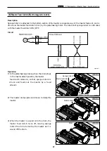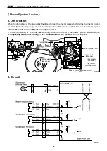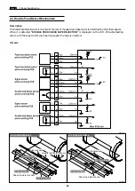
Timing
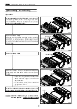
If the master eject jam sensor is not actuated during the first platemaking, it is judged as a master ejection
error.
49
x
Platemaking / Master Feed / Ejection Section
chap.2
2. Rotation Control of the Eject (Roll-up) Motor
If the eject motor is kept rotating when the master tip end is pulled to the ejection box in the plate
detachment process, the drum is actuated by the master and the stop position slips. To prevent this, the
eject motor is stopped when the master is detected by the master eject jam sensor. (If the master is not
detected by the master eject jam sensor, the eject motor is stopped by the timer.)
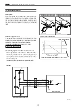
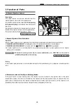
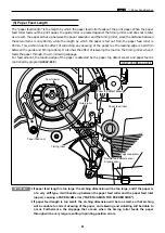
(1) Master Ejection Sensor
Description
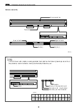
The used master core sensor detects that the
master ejection core is set in the ejection box.
The master ejection sensor becomes
"Photopassing
\
Photointerrupting"
and detects that the ejection
box is full.
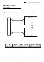
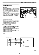
Mechanically actuated, the master eject jam sensor
detects if the master is drawn into the ejection box.
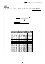
The sensor status is checked in HELP - 009.
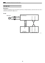
1. Master Ejection Error Detection
Operation
When a master ejection error is detected, Then the following displays and operations are performed:
2
"MASTER EJECTION ERROR"
is displayed on the LCD panel and printing is not processed.
2
"MASTER EJECTION ERROR"
is cleared with the
(
RESET
) key ,
(
STOP
) key pressed.
2
A master ejection error is not detected for one platemaking soon after a plate ejection error or master
setting error is detected.
¡
If incorrect sensing occurs due to sensor malfunction, etc., HELP-061 can be used to
prohibit plate ejection error sensing.
IMPORTANT :
3. Function of Parts
HELP-061
\
see p.268
HELP-009
\
see p.216
R8S02029
Master eject
jam sensor
Used master
full sensor
Used master
core sensor
Summary of Contents for DP-S Series
Page 1: ......
Page 9: ......
Page 11: ......
Page 16: ...x Dimensions chap 1 15 R8S01001 xDimensions 622 1360 510 228 1080 710 980 688 370 mm...
Page 22: ...v Part Names and Their Functions chap 1 21 44000A1e 2A 2B 2C R8S01006a 2Detailed drawing...
Page 33: ...32 z Scanner Section chap 2 Circuit R8S02E03e...
Page 87: ...86 m Drum Section chap 2 2 Circuit R8S02E30...
Page 171: ...170 MEMO...
Page 193: ...192 MEMO...
Page 195: ...194 z Help mode List chap 7 z HELP Mode List...
Page 243: ...242 c HELP Mode Function and Operation Procedures chap 7...
Page 270: ...269 c HELP Mode Function and Operation Procedures chap 7...
Page 281: ...280 MEMO...
Page 293: ...292 z Electrical Parts Layout and Their Functions chap 9 MEMO...
Page 295: ...309 294 x Overall Wiring Layout chap 9 Overall Wiring Layout 1 Main PCB 2 2...
Page 297: ...311 296 x Overall Wiring Layout chap 9 Overall Wiring Layout 2 Drive PCB 2 2...


