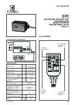
ADJUSTMENTS
Identification P1
P2
P3
P4
code
GAIN RAMP OFFSET SWITCHING
[mA] [mA]
[mA] [mA]
EPC - 110
800
200
EPC - 111 800
100
EPC - 114
800
400
EPC - 120 1200
200
EPC - 130 1600
200
6 - START UP AND CONTROL SETTINGS
If required, settings can be modified as follows:
a) OFFSET CURRENT REGULATION
– Set potentiometer “P1” to minimum.
– Enter the maximum reference signal value (+10V).
– Set potentiometer “P3” so that the valve is positioned at the
start of the work zone.
b) SCALE FACTOR REGULATION
– Enter the maximum reference signal value (+10V).
– Set potentiometer “P1” so that the controlled hydraulic
parameter reaches the maximum required value.
NOTE: The maximum current value must be compatible with
the maximum current prescribed by the technical table of
the connected proportional valve.
c) RAMP REGULATION
– Set potentiometer “P2” to smooth valve response according to
reference signal variations.
EPC
SERIES 10
5 - DEFAULT CONDITIONS
The electronic control unit is supplied factory-set.
Standard settings are:
regulation at
minimum
regulation at
minimum
89 110/101 ED
3/4
3.3 - P3 - OFFSET (Offset current regulation)
Potentiometer “P3” enables regulation of the offset current of the
valve.
This is used to eliminate the valve insensivity zone (dead zone).
The offset current is activated when the reference signal exceeds
the threshold of + 150 mV.
The offset is not active and only the polarization current equal to 25
mA is present beneath this threshold.
NOTE:
The variation of the set value of the offset current causes a
corresponding variation of the scale factor value setted on P1
potentiometer.
Adjustment range = 0
÷
50 % of maximum current
Single turn potentiometer - Rotate clockwise to increase current.
3.4 - P4 - SWITCHING
(PWM frequency regulation)
It is possible to change the switching frequency (PWM) by acting on
the trimmer P4.
The setting range is from 140 to 400 Hz.
An appropriate switching frequency adjustment allows reduction of
the valve hysterisis value.
Single turn potentiometer - Clockwise rotation to increase the
frequency.
NOTE: The potentiometer setting is sealed with a red coating
and it must never be adjusted by the user.
4 - INSTALLATION
The connector type electronic unit is suitable for direct assembly on
the solenoid of the relative proportional valve.
The 4-core connection cable (0,5 mm
2
individual wire section) is
supplied pre-wired and in a standard length of 2,5 m (DIN 47100
standard).
NOTE 1
To observe EMC requirements it is important that the control unit
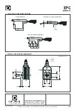
electrical connection is in compliance with the wiring diagram of par. 7.
As a general rule, the valve and the electronic unit connection wires
must be kept as far as possible from interference sources (e.g.
power wires, electrical motors, inverters and electrical switches).
In environments that are critical from the electromagnetic interference
point of view, a complete protection of the connection wires can be
requested.


