Start-up Manual
89475/119 ETM
14
Duplomatic MS S.p.A.
All rights reserved.
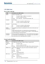
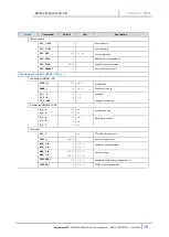
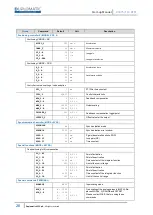
LED definitions
First section with USB
LEDs
Description of the LED function
GREEN
Identical to the READY output.
OFF:
No power supply or ENABLE is not activated
ON:
System is ready for operation
Flashing:
Error discovered - Only active when SENS = ON
YELLOW A
STATUS output.
OFF:
The axis 1 is outside the INPOS window.
ON:
The axis 1 is within the INPOS window.
YELLOW B
STATUS output.
OFF:
The axis 2 is outside the INPOS window.
ON:
The axis 2 is within the INPOS window.
GREEN +
YELLOW A+B
Chasing light (over all LEDs): The bootloader is active. No normal functions are
possible.
All LEDs flash shortly every 6 s: An internal data error was detected and
corrected automatically! The module still works regularly. To acknowledge the
error the module has to be cycle powered.
YELLOW A +
YELLOW B
Both yellow LEDs flash oppositely every 1 s: The nonvolatile stored parameters
are inconsistent! To acknowledge the error, the data have to be saved with the
SAVE command or the corresponding button in the WPC.
Second section (fieldbus)
LEDs
Description of the LED function
GREEN x2
besides the
jacks
Green LEDs shows link pulses. It flickers if there is network traffic
OFF:
No power supply
ON:
System is ready for operation
Flashing:
Ethernet connection is active. Blinks if there is data transmission
GREEN on top
The green LED indicates the status of the central communication processor:
OFF:
Initializing
Flashing:
wait for data
Flickering:
Failure
ON:
Connected and active
RED on top
The red LED indicates a failure state
OFF:
No Error
Flashing:
Node flash test
ON:
Failure in the data communication


