Start-up Manual
89475/119 ETM
20
Duplomatic MS S.p.A.
All rights reserved.
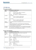
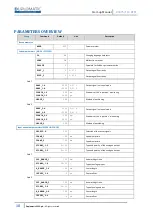
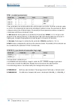
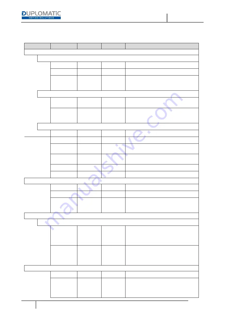
Group
Command
Default
Unit
Description
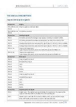
Positioning controller 2 (MODE = POS_2)
Positioning VMODE = NC
ACCEL_2
250 mm/s²
Acceleration
VMAX_2
50 mm/s
Maximum velocity
V0_2:A
10 1/s
Loop gain
V0_2:B
10 1/s
V0_2:RES
1 -
Loop gain resolution
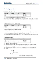
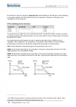
Positioning VMODE = SDD
A_2:A
100 ms
Acceleration time
A_2:B
100 ms
D_2:A
25 mm
Deceleration stroke
D_2:B
25 mm
D_2:S
10 mm
Controller common settings / valve adaption
PT1_2
1 ms
PT1-filter time constant
CTRL_2
SQRT1 -
Control characteristic
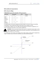
MIN_2:A
0 0,01 %
Deadband compensation
MIN_2:B
0 0,01 %
MAX_2:A
10000 0,01 %
Output scaling
MAX_2:B
10000 0,01 %
TRIGGER_2
200 0,01 %
Deadband compensation trigger point
OFFSET_2
0 0,01 %
Offset value for the output
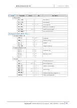
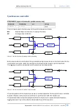
Synchronisation Controller (MODE = SYNC)
SYNCMODE
MS -
Synchronization mode
SYNCWIN
5000 µm
Synchronization error window
SYNC:P
25 mm
P gain (deceleration stroke, SDD)
SYNC:V0
10
s
-1
Loop gain (NC)
SYNC:T1
80 ms
Time constant
Special functions (MODE = EXTRA)
Fine positioning / drift compensation
DC_1:AV
0 0,01 %
Point of activation
DC_1:DV
0 0,01 %
Point of deactivation
DC_1:I
2000 ms
Time constant of the integrator function
DC_1:CR
500 0,01 %
Limit of the control range
DC_2:AV
0 0,01 %
Point of activation
DC_2:DV
0 0,01 %
Point of deactivation
DC_2:I
2000 ms
Time constant of the integrator function
DC_2:CR
500 0,01 %
Limit of the control range
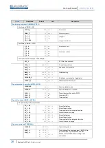
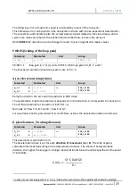
Special commands (TERMINAL)
AINMODE
EASY -
Input scaling mode
AIN_1:X
A: 1000 -
Free scaling of the analogue inputs (MATH). Re-
AIN_2:X
B: 1000 -
places SIGNAL, N_RANGE and OFFSET.
C:
0
X:
V
0,01 %
-
Please contact W.E.St. before using these
commands.


