Start-up Manual
89475/119 ETM
34
Duplomatic MS S.p.A.
All rights reserved.
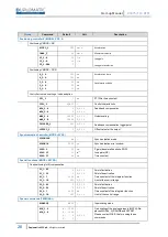
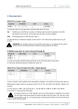
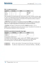
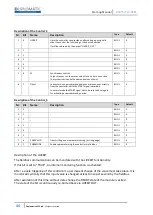
SYNC (control parameters)
Commands
Parameter
Units
Group
SYNC:P
X
SYNC:V0
X
SYNC:T1
X
x= 1… 10
000
x= 1… 400
x= 1… 300
mm
s
-1
ms
SYNC / SDD
SYNC / NC
SYNC
These parameters are used to optimize the synchronization controller. The SYNC-controller works
as a PT1 or PI compensator for optimized controlling of hydraulic drives. The parameter T1 effects
a delayed action of the SYNC Controller. The stability of the compensator could be increased in
critical cases with the up streamed T1 Filter.
In
SDD-mode
the braking distance is specified by the parameter
SYNC:P,
in mm. The gain, that
depends on the stopping distance, is calculated internally. Short braking distances will result in
higher gains. A longer stopping distance should be given in the event of instability.
In
NC-mode
, the loop gain is entered by the parameter
SYNC:V0
, specified in s
-1
(1 / s).
SYNC:T1
causes a delayed action of the synchronized controller. The stability of the controller can
be increased by the upstream T1-filter in critical cases.
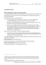
SYNCWIN (synchronization monitoring range)
Command
Parameter
Unit
Group
SYNCWIN_1:i x
SYNCWIN_2:i
x = 2… 200000
µm
SYNC
This parameter is entered in µm.
The SYNCWIN command defines a range for which the
𝐺𝐿 − 𝐸𝑅𝑅𝑂𝑅
message is generated.
This function monitors the difference between the command and the actual position.
The controlling process is not influenced by this message and remains active.
SYNCMODE AV
Both axes are monitored. The average value of both axes is
‘
demand value
’
SYNCMODE MS
The difference between both axes is monitored. SYNCWIN_1 = SYNCWIN_2.

