background image


Start-up Manual   

89475/119 ETM 


8


Duplomatic MS S.p.A.

 All rights reserved. 


 USE AND APPLICATION


Installation instructions 

This module is designed for installation in a shielded EMC housing (control cabinet). All cables 
which lead outside must be screened; complete screening is required. It is also required that no d 
strong electro-magnetic interference sources are installed nearby when using our control 
modules. 

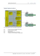
Typical installation location: 24 V control signal area (close to PLC)  
The devices must be arranged in the control cabinet so that the power section and the signal 
section are separate from each other.  
Experience shows that the installation space close to the PLC (24 V area) is most suitable.  
All digital and analogue inputs and outputs are fitted with filters and surge protection in the 
device. 

The module should be installed and wired in accordance with the documentation bearing in mind 
EMC principles. If other consumers are operated with the same power supply, a star-connected 
ground wiring scheme is recommended. The following points must be observed when wiring: 


The signal cables must be laid separately from power cables. 


Analogue signal cables 

must be shielded


All other cables must be screened if there are powerful interference sources (frequency 
converters, power contactors) and cable lengths > 3 m. Inexpensive SMD ferrites can be used 
with high-frequency radiation.  


The screening should be connected to PE (PE terminal) as close to the module as possible. The 
local requirements for screening must be considered in all cases. The screening should be 
connected to at both ends. Equipotential bonding must be provided where there are 
differences between the connected electrical components.  


With longer lengths of cable (> 10 m), the diameters and screening measures should be 
checked by specialists (e. g. for possible interference, noise sources and voltage drop). 
Particular care is required with cables of over 40 m in length, the manufacturer should be 
consulted if necessary. 

A low-resistance connection between PE and the mounting rail should be provided. Transient 
interference is transmitted from the module directly to the mounting rail and from there to the 
local earth.  

Power should be supplied by a regulated power supply unit (typically a PELV system complying 
with IEC 364-4-4* secure low voltage). The low internal resistance of regulated power supplies 
gives better interference voltage dissipation, which improves the signal quality of high-resolution 
sensors in particular. Switched inductances (relays and valve coils) connected to the same power 
supply must always be provided with appropriate overvoltage protection directly at the coil. 


Summary of Contents for EWM-2SS-DAD/22E-PN

Page 1: ...89475 119 ETM EWM 2SS DAD 22E Profinet Interface Digital Card Start up manual Duplomatic MS S p A...

Page 2: ...YSTEM 21 LG Changing the language for the help texts 21 SENS Malfunction monitoring 21 PASSFB Password fieldbus 22 EOUT Output signal READY OFF 22 HAND Manual speed 22 POSWIN in position monitoring ra...

Page 3: ...ve zero offsets 32 Synchronous controller 33 SYNCMODE operation mode synchronous run 33 SYNC control parameters 34 SYNCWIN synchronization monitoring range 34 Special functions 35 Drift compensation h...

Page 4: ...iterature about EWM 2SS DAD 22E PN and its start up can be found in Technical catalogue 89475 ED edition 119 Software pack EWMPC 20 For installation start up commissioning and maintenance use only ski...

Page 5: ...be connected and put into operation by trained specialist staff The instruction manual must be read with care The installation instructions and the commissioning instructions must be followed Guarante...

Page 6: ...gital output too Typical applications Positioning control or synchronization control with hydraulic axes Features Two independent positioning axes Can be combined for synchronized control Command posi...

Page 7: ...9475 119 ETM Duplomatic MS EWM 2SS DAD 22E PN Start up Manual 89475 PN 119 ETM Mar 2019 7 Device description 1 Din Rail Clip 2 USB interface 3 LED Ready axis 1 axis 2 4 ProfiNet Fieldbus ports 5 Commu...

Page 8: ...werful interference sources frequency converters power contactors and cable lengths 3 m Inexpensive SMD ferrites can be used with high frequency radiation The screening should be connected to PE PE te...

Page 9: ...119 ETM Mar 2019 9 Typical system structure This minimal system consists of the following components 1 Proportional valve with integrated electronics 2 Drive e g hydraulic cylinder 3 Position sensors...

Page 10: ...output indicates that the system is generally ready for operation After setting the START signal the preset command value will be taken over The axis immediately will drive to this new command positio...

Page 11: ...cy must be considered when designing the system The electronic limitations lie mainly in the resolution of the analogue signals although with our modules a resolution of 0 01 only needs to be consider...

Page 12: ...hich is uncritical for the application Control signals Check the control signal with a voltmeter The control signals PIN 15 to PIN16 and PIN19 to PIN20 lies in the range of 10V In the current state it...

Page 13: ...0 10V or 4 20 mA scalable PIN 15 16 Valve control signal axis 1 Type of signal and polarity can be selected by the parameter SIGNAL U1 PIN 19 20 Valve control signal axis 2 Type of signal and polarit...

Page 14: ...d automatically The module still works regularly To acknowledge the error the module has to be cycle powered YELLOW A YELLOW B Both yellow LEDs flash oppositely every 1 s The nonvolatile stored parame...

Page 15: ...SS DAD 22E PN 89475 119 ETM Duplomatic MS EWM 2SS DAD 22E PN Start up Manual 89475 PN 119 ETM Mar 2019 15 Block diagram voltage current 15 12 10 V U1 20 19 18 10 V U2 19 12 18 U1 U2 4 20 mA 4 20 mA GN...

Page 16: ...Start up Manual 89475 119 ETM 16 Duplomatic MS S p A All rights reserved Typical wiring...

Page 17: ...outputs voltage Signal resolution Current Signal resolution V mA mA 2 x 0 10 Differential output 5 max load 0 024 4 20 390 Ohm maximum load 0 024 SSI interface RS 422 specification 150 kBaud Controll...

Page 18: ...Method of positioning Axis 2 HAND_2 A HAND_2 B 3330 3330 0 01 0 01 Output signal in manual mode POSWIN_2 S POSWIN_2 D 200 5000 m m Windows of the in position monitoring VMODE_2 SDD Methodofpositioning...

Page 19: ...ontroller 1 MODE POS_1 Positioning VMODE NC ACCEL_1 250 mm s Acceleration VMAX_1 50 mm s Maximum velocity V0_1 A 10 1 s Loopgain V0_1 B 10 1 s V0_1 RES 1 Loop gain resolution Positioning VMODE SDD A_1...

Page 20: ...OFFSET_2 0 0 01 Offset value for the output Synchronisation Controller MODE SYNC SYNCMODE MS Synchronization mode SYNCWIN 5000 m Synchronization error window SYNC P 25 mm P gain deceleration stroke SD...

Page 21: ...LG X x DE EN SYSTEM Either German or English can be selected for the help texts Deutsch DE English GB After changing the language setting the ID button in the menu bar must be pressed to see the modi...

Page 22: ...If a null value 12 mA is to be output in the event of an error EOUT must be set to 11 The output value defined here is stored permanently independent from the parameter set The effects should be anal...

Page 23: ...used to monitor the following error of NC mode VMODE Selecting the control mode Command Parameters Unit Group VMODE_1 X VMODE_2 X x SDD NC SYSTEM The fundamental control structure can be changed with...

Page 24: ...nt regardless of external influences due to the profile demand Because of continuous control it is necessary not to run at 100 speed as otherwise the errors cannot be corrected 70 80 of the maximum sp...

Page 25: ...speed demand Command Parameters Unit Group VRAMP_1 X VRAMP_2 X x 1 2000 ms IO_CONFIG The rate of change of external speed demand can be limited by these ramp times In NC mode these parameters should...

Page 26: ...nput signals voltages or current and to define the direction of the signal This command is available for analogue feedback inputs OFF Deactivation of the input N_RANGE X nominal range of the sensor Co...

Page 27: ...be set to 100 This makes possible to scale rotational sensors Take the data from the sensor s data sheet SSI BITS number of bits Command Parameter Unit Group SSI BITS X x 8 31 bit IO_CONFIG The number...

Page 28: ...is defined by the drive system and should be specified as precisely as possible not too high under any circumstances The speed is scaled by the external speed demand set via Profibus The command is ac...

Page 29: ...on ramp time Command Parameters Unit Group A_1 I X A_2 I X i A B x 1 5000 ms POS_1 SDD POS_2 SDD Ramp function for the 1st and 3rd quadrants in SDD mode The acceleration time for positioning is depend...

Page 30: ...s control valves and servo valves require either LIN or SQRT1 function regardless of the application The progressive characteristic of the SQRT1 function has better positioning accuracy but can also l...

Page 31: ...e commands A kinked volume flow characteristic is used instead of the typical overlap step for the position controls The advantage is a better and more stable positioning behaviour With this compensat...

Page 32: ...e of high speeds and very fast valves The PT1 filter can improve the damping rate and allows therefore higher loop gains Requirements for the use are The natural frequency of the valve should be equal...

Page 33: ...al positions are checked The calculated average value serves as command value for the synchronous controller which has an effect on both axes while trying to synchronize them The lagging one will be a...

Page 34: ...Short braking distances will result in higher gains A longer stopping distance should be given in the event of instability In NC mode the loop gain is entered by the parameter SYNC V0 specified in s 1...

Page 35: ...onal to the positioning error In opposite to point one and two the positioning error generated by forces can vary from cycle to cycle How does the drift compensation high accurate positioning work 1 T...

Page 36: ...ime has to be determined experimentally Starting with higher values is recommended The integration time usually has to be determined by experiments For this it is recommended to start with a long time...

Page 37: ...n will be limited CR control range by this parameter PROCESS DATA monitoring The process data are variables which can be continuously observed on the monitor or on the oscilloscope Command Description...

Page 38: ...the device is in an operable state and there is communication between the module and the EWMPC 20 software Furthermore the valve control parameterization has been set with the assistance of the valve...

Page 39: ...system oscillates on the spot The system is working and also actuating the valve Various potential problems could be The parametrisation is not yet adjusted to the system gain too high There is sever...

Page 40: ...network can be set up in star tree line or ring topology ProfiNet IO is based on the Fast Ethernet standard transmission with 100 Mbit s The transmission media are copper cables CAT5 For the IP20 env...

Page 41: ...the output signal The value of 0x3fff corresponds with 100 speed Data sent to the device The module is controlled with control PDO consisting of the following bytes a 32 byte data frame is used Index...

Page 42: ...tion_1 Low LSB 9 8 Velocity_1 High UINT16 0 0x3fff 0 100 10 9 Velocity_1 Low 11 10 Position_2 High MSB UINT32 0 10000000 0 001 mm 12 11 13 12 14 13 Position_2 Low LSB 15 14 Velocity_2 High UINT16 0 0x...

Page 43: ...BOOL 0 8 7 Enable_1 General activation of the axis 1 Malfunction monitoring and output signal get activated in combination with the hardware enable BOOL 0 Description of the Control_2 Nr Bit Name Des...

Page 44: ...nal has to be reset and set again for activating a new command position BOOL 0 Description of the Control_4 Nr Bit Name Description Type Default 1 0 BOOL 0 2 1 BOOL 0 3 2 BOOL 0 4 3 BOOL 0 5 4 BOOL 0...

Page 45: ...15 14 16 15 17 16 Internal command position 2 High MSB Internal command position 2 Low LSB UINT32 0 10000000 0 001 mm 18 17 19 18 20 19 21 20 Index Subi ETC Name Description 6000 1 Status_1 The state...

Page 46: ...gnals Attention Inverted signal an error exists if the bit is not set BOOL 0 2 1 BOOL 0 3 2 BOOL 0 4 3 BOOL 0 5 4 Syncwin Synchronous run monitoring Message for being within the preset window for sync...

Page 47: ...readiness of the axis ENABLE signals are available and no error was detected BOOL 0 Description of the status byte 3 Nr Bit Name Description Type Default 1 0 BOOL 0 2 1 BOOL 0 3 2 BOOL 0 4 3 BOOL 0 5...

Page 48: ...ameterization Attention A missing para ready bit means parameterization was not done Storing Same procedure as parameterizing standard parameters Selecting 2100 as address written value does not matte...

Page 49: ...13 MIN_1 A 0x0000 0x1770 14 0x2014 MIN_1 B 0x0000 0x1770 15 0x2015 TRIGGER_1 0x0000 0x0BB8 16 0x2016 OFFSET_1 0xF060 0x0FA0 17 0x2021 POSWIN_2 S 0x0002 0x30D40 18 0x2022 POSWIN_2 D 0x0002 0x30D40 19 0...

Page 50: ...Start up Manual 89475 119 ETM 50 Duplomatic MS S p A All rights reserved...

Reviews: