background image

I-2

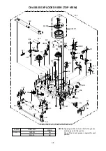
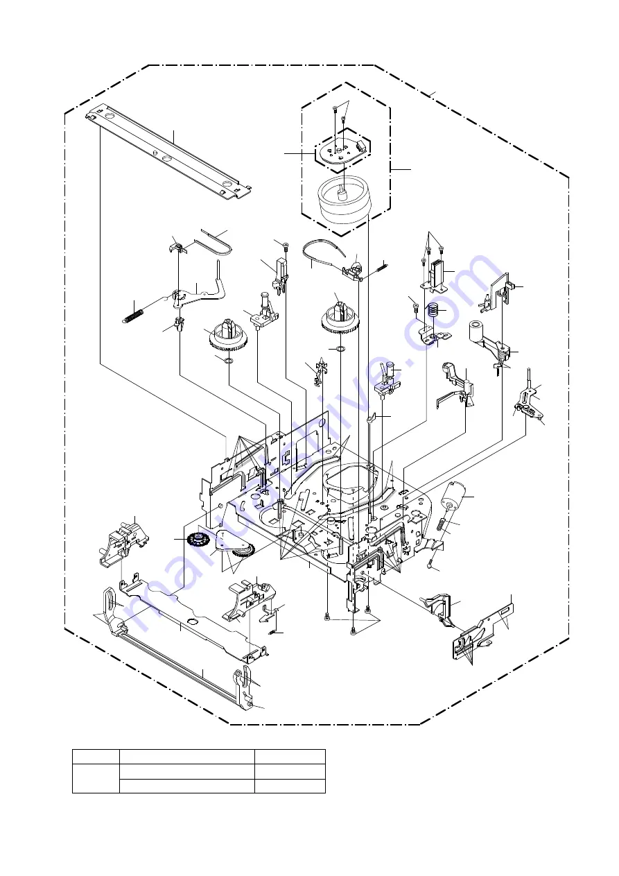
CHASSIS EXPLODED VIEW (TOP VIEW)

312

315

UN4001

M2003

502

504

H5001

503

306

305

332

507

335

342

322

508

324

348

506

304

M101

501

H5002

323

508

341

331

334

333

314

302

301

313

307

300

317

309

336

346

345

321

319

320

AB

316

318

325

347

AA

AB

AB

AB

AA

AA

AA

AA

AA

AB

AB

AB

AB

AB

AB

AB

AB

Applying positions AA and AB for the grease 
are displayed for this section.
Check if the correct grease is applied for each 
position.

NOTE:

PART NO.

CLASS

MARK

GREASE

G-555G

AA

MG-33

AB

Summary of Contents for DBV4403

Page 1: ...thout notice DBV4403 VIDEO CASSETTE RECORDER SUPPLEMENT MFR S VERSION D This SUPPLEMENT must be used together SERVICE MANUAL for MVR4052 All other test and repair procedures are as shown in the ORIGIN...

Page 2: ...04 712WPJB163 FLAP 712WPJB586 FLAP 610 735WPDA445 BUTTON PLAY STOP 735WPDA559 BUTTON PLAY STOP 611 711WPDA389 PLATE DISPLAY 711WPDA519 PLATE DISPLAY 617 722A08A105 SHEET RATING 722552A024 SHEET RATING...

Page 3: ...ge for safety Therefore the part which is replaced should be used the part which has the same character Especially as to the important parts for safety which is indicated in the circuit diagram or the...

Page 4: ...CCD HEAD AMP SYSTEM CONTROL SERVO TUNER HI FI DEMODULATOR OPERATION POWER PRINTED CIRCUIT BOARDS SYSCON OPERATION SCHEMATIC DIAGRAMS Y C AUDIO CCD HEAD AMP SYSTEM CONTROL SERVO POWER OPERATION TUNER...

Page 5: ...nnel 3 or 4 ch Level Impedance 66dBu 75ohm Sound Selector No Stereo Dual TV Sound Yes G 3 Power Power Source AC 120V 60Hz DC Power Consumption Power On at AC 9W at 120V 60Hz Stand by at AC 1 8W at 120...

Page 6: ...Rec Set Yes Auto Repeat On Off Yes SAP On Off Yes CH Set Up Yes TV CATV Yes Auto CH Memory Yes Add Delete Yes Pin Code Registration No System Set Up No Clock Set Yes Calendar 12H Language Yes No Nois...

Page 7: ...Yes Pause Still Yes Stop Yes Rec OTR Yes Eject No Counter Reset Yes Speed Yes Timer Rec Yes TV Monitor No Quick View No Program No Slow Yes Auto Tracking Yes Set Tracking Yes Set Tracking Yes Menu Ye...

Page 8: ...ter No Guarantee Card No Warning Sheet No Circuit Diagram No Antenna Change Plug No Service Facility List No Important Safeguard No Dew AHC Caution Sheet No AC Plug Adapter No Quick Set up Sheet No AC...

Page 9: ...lap to 90 and flex in direction of arrow A at the same time slide in direction of arrow B Then lift in direction of arrow C A C B Flap Fig 1 2 B1 1 2 2 1 2 Fig 1 1 B A 1 1 1 Top Cabinet 2 2 2 2 3 3 3...

Page 10: ...move the Locker R 1 2 3 Link Ass y NOTE 1 2 In case of the Locker R installation check if the two positions of Fig 2 3 B are correctly locked When you install the Cassette Side R be sure to move the L...

Page 11: ...ding Motor Remove the Worm 1 2 3 Fig 2 6 A Screw Torque 3 0 5kgf cm Loading Motor 1 Main Chassis Worm NOTE 1 In case of the Worm installation check if the value of the Fig 2 6 B is correct Fig 2 6 B 1...

Page 12: ...ouch the section A of S Reel and T Reel Use gloves Refer to Fig 2 9 A Do not adhere the stains on it When you install the reel clean the shaft and grease it MG 33 If you do not grease noise may be hea...

Page 13: ...ch the A C Head Use gloves When you install the A C Head Spring install as shown in Fig 2 11 B When you install the A C Head tighten the screw 1 first then tighten the screw 2 finally tighten the scre...

Page 14: ...move the Main Rod Tension Lever Loading Arm S Ass y and Loading Arm T Ass y 1 Main Rod Main Loading Gear Tension Lever Loading Arm T Ass y Loading Arm S Ass y Fig 2 18 A 2 13 AHC ASS Y CYLINDER UNIT A...

Page 15: ...ig 2 18 B Fig 2 18 C Cassette Guide Post Cassette Guide Post 2 17 Remove the Polyslider Washer 1 Remove the Clutch Ass y and Ring Spring Remove the Clutch Lever Remove the Coupling Gear Coupling Sprin...

Page 16: ...a blower type IC desoldering machine Refer to Fig 3 2 2 Fig 3 2 NOTE Do not add the rotating and the back and forth directions force on the IC until IC can move back and forth easily after desoldering...

Page 17: ...in tip Soldering Iron NOTE When the IC leads are bent during soldering and or repairing do not repair the bending of leads If the bending of leads are repaired the pattern may be damaged So be always...

Page 18: ...op Frequency Generator Front Loading Switch Frequency Modulation Frequency Sub Carrier Forward Generator Ground High Pass Filter I K L M N O P R S H SW Hz IC IF IND INV KIL L LED LIMIT AMP LM LDM LP L...

Page 19: ...or Separation Transistor Tracking Trick Playback Test Point Unregulated Volt Voltage Controlled Oscillator Video Intermediate Frequency Vertical Pulse Voltage Display Video Playback Variable Resistor...

Page 20: ...Tracking to the center position Refer to the MECHANICAL ADJUSTMENT GUIDE ROLLER and ELECTRICAL ADJUSTMENT PG SHIFTER Press the ATR button on the remote control for more than 2 seconds during PLAY Make...

Page 21: ...Replace when rolling becomes abnormal Clean the Head CLEANING NOTE After cleaning the heads with isopropyl alcohol do not run a tape until the heads dry completely If the heads are not completely dry...

Page 22: ...pe For 2 heads model VHS Alignment Tape For 2 heads model VHS Alignment Tape For 2 heads model VHS Alignment Tape For 4 heads model VHS Alignment Tape For 4 heads model VHS Alignment Tape For 4 heads...

Page 23: ...Set the unit to the PLAY mode Install the tentelometer as shown in Fig 1 3 Confirm that the meter indicates 20 2gf in the beginning of playback 1 2 USING A CASSETTE TYPE TORQUE TAPE JG100A 1 2 3 After...

Page 24: ...3 2 as shown in Fig 2 1 B even if you press the Tracking Button to move the envelope The envelope waveform will begin to decrease when you press the Tracking Button Adjust the PG shifter during playba...

Page 25: ...to TP4001 CH 2 to TP1002 and CH 3 to HOT side of Audio Out Jack Playback the VHS Alignment Tape JG001S or JG001T Refer to SERVICING FIXTURE AND TOOLS Press and hold the Tracking Auto button on the rem...

Page 26: ...USTMENT PARTS LOCATION GUIDE 5 6 7 8 9 10 1 2 3 4 1 Tension Connect 2 Tension Arm 3 Guide Roller 4 Audio Control Head 5 X value adjustment driver hole 6 7 8 9 10 P4 Post T Brake Spring T Reel S Reel A...

Page 27: ...1 1 B Read and perform this adjustment when repairing the circuits or replacing electrical parts or PCB assemblies 1 BASIC ADJUSTMENT 1 2 3 4 D2 1 Connect CH 1 on the oscilloscope to TP1002 and CH 2...

Page 28: ...2 ELECTRICAL ADJUSTMENT PARTS LOCATION GUIDE SYSCON PCB T501 ELECTRICAL ADJUSTMENTS D2 2 J4205 J4204 J4203 VR1001 TP1001 TP4001 TP1002 TP4201 J4201 TU6001...

Page 29: ...Y LPF YNR COMB N L DEEM NC1 Y C MIX SYNC SEP VCA CLAMP 1 2 FBC Chara INS 6dB P R P R V AGC T4001 CLAMP EQ AMP LINE AMP MUTE ALC Y C_CS IIC_DATA IIC_CLK H AMP_SW C ROTARY H SW ENV DET COMP DUMMY_V SYNC...

Page 30: ...ET 4FSC AFT S CURVE TV VCR A_OUT_MUTE L VIDEO_OUT TUNER L IIC_CLK IIC_DATA MODE_VCC BOT H 3 1 4 EOT H 12 P CON 5V BOT SENSOR Q1008 H SW 24 C SYNC 54 H SW C SYNC IIC_CLK IIC_DATA V REC ST H AUDIO_MUTE...

Page 31: ...OUT 3 6 AUDIO_OUT_L TV VCR P CON 12V FRONT AV JACK VIDEO J4203 2 FRONT_V_IN TUNER_V 5 3 Y C AUDIO CCD HEAD AMP FRONT_A_IN R Q4204 MUTE SW Q4203 MUTE SW Q4202 MUTE SW TUNER_A 11 IIC_CLK 12 IIC_DATA 23...

Page 32: ...1 22 62 61 AUDIO_OUT_L HIFI_H SW RF_CONV_A OUT TUNER_A AUDIO_MUTE H V REC_ST H HIFI_ENV DET IIC_CLK IIC_DATA AUDIO_OUT_R ST_SELECT FRONT_A_IN L FRONT_A_IN R HF2 HF_COM HF1 FROM_NORMAL_A TO_NORMAL_A TU...

Page 33: ...A431 VOLTAGE CTL IC 3 1 PHOTO COUPLER L501 AC IN Q509 D505 D508 D523 D528 2 7 Q512 P CON 12V SW Q513 P ON SW P CON 5V SW F501 P CON 5V P CON 12V POWER_FAIL POWER_ON L AT 12 6V 32V SYSCON SERVO 10 AT 5...

Page 34: ...6004 W817 C4209 Q4201 R4201 R4211 TP4201 W069 C4030 C4014 R4005 VR1001 L4001 W137 W111 W049 C4059 C4012 W812 W110 W139 W066 W136 W047 SW6001 C4201 W064 TU6001 W067 W141 SW1001 W094 W024 W113 W115 TP10...

Page 35: ...4005 C4006 C5546 C5545 C5542 C5541 C5524 C5515 C5508 C5507 C5506 C5553 C5504 C5514 Q4202 C6014 R4202 R4206 R6006 R4212 R5513 R5502 R4012 C4019 C4015 C4022 R4013 C4023 C4028 R4017 R4019 C4029 C4032 R40...

Page 36: ...5 47uH L4006 47uH RECORD COLOR SIGNAL RECORD LUMINANCE SIGNAL PLAYBACK COLOR SIGNAL PLAYBACK LUMINANCE SIGNAL AUDIO SIGNAL PB AUDIO SIGNAL REC TUNER VIDEO SIGNAL H SW ENV DET COMP H AMP_SW C ROTARY Y...

Page 37: ...L LED_VCC POWER_ON L AT 5V M CON IIC_DATA_A IIC_CLK_A AFT S CURVE A_OUT_MUTE L TV VCR VIDEO_OUT TUNER_L P CON 5V AT 5 2V AT 12 6_V GND GND GND IIC_DATA IIC_CLK V REC_ST H HIFI_ENV DET TUNER_L 4FSC C S...

Page 38: ...ED WITH THE DIGITAL TESTER NOTE THE DC VOLTAGE AT EACH PART WAS OF PRINTING AND SUBJECT TO CHANGE WITHOUT NOTICE NOTE THIS SCHEMATIC DIAGRAM IS THE LATEST AT THE TIME C517 1 50V KA C522 220 16V YK C52...

Page 39: ...3 CP651 A2001WV2 3P 1 2 3 DURING PLAYBACK MEASURED WITH THE DIGITAL TESTER NOTE THE DC VOLTAGE AT EACH PART WAS OF PRINTING AND SUBJECT TO CHANGE WITHOUT NOTICE NOTE THIS SCHEMATIC DIAGRAM IS THE LAT...

Page 40: ...1K 1 4W R4207 1K 1 4W R4209 75 R4210 100 R4206 390 R4211 1K 1 4W R4204 10K R4205 10K R4212 390 R4202 75 R4201 470 1 2W C6008 220 6 3V YK C6003_1 10 16V KA C4201 470 6 3V YK C4209 10 16V KA Q4204 2SC24...

Page 41: ...V KA C5527 10 16V KA TP5501 HIFI ENV W817 L5502 100uH L5501 100uH L5504 22uH AUDIO SIGNAL PB AUDIO SIGNAL REC FSC IIC_CLK IIC_DATA TUNER_A AUDIO_MUTE H 5V FRONT_A_IN R FRONT_A_IN L AUDIO_OUT R AUDIO_O...

Page 42: ...651 FROM GND CP1001 CD1002 CP4002 AE HEAD AE HEAD CTL CTL AUDIO REC AUDIO PB AE HEAD AE HEAD FFC AE AUDIO CTL CTL AUDIO REC AUDIO PB H5001 HEAD AUDIO CONTROL ASS Y CONTROL VMA224 SYSCON PCB PCB010 FSC...

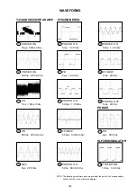
Page 43: ...ERVO 3 PB 1ms 100mV div 8 POWER ON 500 s 1 0V div Y C AUDIO CCD HEAD AMP 1 POWER ON 10 s 500mV div 2 POWER ON 100ns 100mV div 4 PB 500 s 200mV div 5 REC 5 s 20V div 6 POWER ON 5ms 1 0V div 9 FF REW 50...

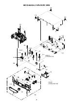
Page 44: ...ICAL EXPLODED VIEW PCB270 OPERATION PCB 602 607 606 701 610 607 611 609 701 605 604 601 PCB010 SYSCON PCB TU6001 T501 614 J4205 608 613 J4201 J4204 J4203 618 612 612 614 616 615 703 617 619 603 702 70...

Page 45: ...02 323 508 341 331 334 333 314 302 301 313 307 300 317 309 336 346 345 321 319 320 AB 316 318 325 347 AA AB AB AB AA AA AA AA AA AB AB AB AB AB AB AB AB Applying positions AA and AB for the grease are...

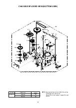
Page 46: ...505 510 338 510 337 340 509 308 344 327 343 326 328 AA AA AB AB AB AA AA AA AA AA AA AA AA AA Applying positions AA and AB for the grease are displayed for this section Check if the correct grease is...

Page 47: ...711WPDA389 PLATE DISPLAY 612 701WPA0680 HOLDER DECK 613 755WPA0020 PLATE COVER POWER 614 85OP700036 HOLDER EOT SENSOR 615 702WSA0083 PLATE BOTTOM 616 85OP700037 HOLDER LED 617 722A08A090 SHEET RATING...

Page 48: ...OA400226 P5 ARM ASS Y H5002 1543D02013 HEAD FULL ERASE HVFHP0032A 314 85OA400230 TENSION ARM ASS Y M101 1596P98001 MOTOR LOADING MXN13FB12K3 315 85OA400231 INCLINED BASE S UNIT M2001 1510S98035 CAPSTA...

Page 49: ...4 D1004 D1VT001330 DIODE SILICON 1SS133T 77 P C BOARD ASSEMBLIES D1005 D1VT001330 DIODE SILICON 1SS133T 77 PCB010 A4F210B010 PCB ASS Y VMA224A D5501 D1VT001330 DIODE SILICON 1SS133T 77 PCB270 A4F212B2...

Page 50: ...M4F2 10B O R NO SPEC NO K184002...

Reviews: