110-275
18
Selecting the Pressure / Flow Rate Display and Units
The Chiller can be set up to display either fluid pressure (in PSI or kPa) or flow rate (in GPM or LPM). Pressing
the Units/Menu Select Button briefly toggles through the available selections.
NOTE:
The metric pressure reading displayed must be multiplied by 100 for the actual kPa value.
NOTE:
The flow rate readout is intended as a reference only. If accurate flow readings are required, an
external flow meter is recommended.
Setting Operational Parameters / Limits
The Chiller’s various operational parameters, such as temperature, flow rate, and pressure alarm values, are all
user-adjustable. They are accessed by pressing and holding the Units/Menu Button until HL appears on the
Pressure/Flow Rate Display. Pressing and releasing the Units/Menu Button once HL appears allows you to scroll
through the various parameters; rotating the Select/Set Knob allows you to change the displayed setting. You can
accept the displayed value by either pressing the Select/Set Knob or allowing the display to timeout.
Operational parameter limit alarms will shut down the compressor, fan, pump, and heaters. Some temperature
values are only displayed and settable in ºC
NOTE:
Some parameters listed may not be included in your version of software.
NOTE:
The Ranges and Default Settings shown are for standard models. Ranges and Default Settings for
your unit may differ depending on the options selected.
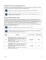
Menu
Item
Description
Choices / Ranges
Default Setting
HL
High Temperature Limit —
Limits the maximum allowable
set point temperature. Audio and visual alarm indicators are
activated when the measured fluid temperature reaches the
HL temperature setting.
NOTE:
EHL will appear on the display if the High Limit value
is set below the current set point.
68° to 104ºF
20° to 40 ºC
95°F
35 ºC
LL
Low Temperature Limi
t — Limits the minimum allowable set
point temperature. Audio and visual alarm indicators are
activated when the measured fluid temperature reaches the
LL temperature setting.
NOTE:
ELL will appear on the display if the Low Limit value is
set above the current set point.
10° to 59°F
-12° to +15°C
0.0ºC
Summary of Contents for DCA203C4
Page 1: ...Operator s Manual DuraChill Air and Water Cooled 2 and 3 HP Chillers 110 275 25 February 2015...
Page 9: ...110 275 8 Rear View Power Switch Power Switch...
Page 36: ...110 275 35 Pump Performance Specifications subject to change without notice...
Page 40: ...110 275 39 Appendix Flow Diagram Air Cooled Chillers...
Page 41: ...110 275 40 Flow Diagram Water Cooled Chillers...
Page 42: ...110 275 41 Wiring Diagram 208 230V 1 Phase Air Cooled Chillers...
Page 43: ...110 275 42 Wiring Diagram 208 230V 380 460V 3 Phase Air and Water Cooled Chillers...

