110-275
21
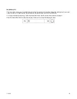
FP
kPa x 100
5.5
NOTE:
Chillers with positive displacement and turbine pumps also incorporate a built-in safety that
automatically maintains fluid pressure below a valve-regulated pressure value. It maintains this maximum
outlet pressure by diverting the flow of process fluid to the reservoir (i.e., begin internally recirculating the
fluid). A maximum pressure value is set at the factory, but is user-adjustable. See “
Adjusting the High
Pressure Bypass Setting
” for information on changing the maximum outlet pressure value.
Minimum Flow Rate (FL)
NOTE:
If flow rates are below 1.5 GPM (6 LPM), this feature is not recommended as nuisance alarms may
result.
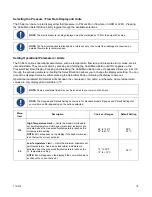
This is the minimum allowable flow rate and can be set in either GPM or LPM (the LED adjacent to the display
indicates the active unit of measure). Should the fluid flow rate drop below the minimum value, the audio and
visual alarms will activate, and the compressor, heater, fan, and pump will turn off.
To change the minimum flow rate value, rotate the Select/Set Knob until the desired flow rate value is displayed
on the Temperature Readout.
With FL set to “0”, the flow alarm is disabled, and the Chiller will continue to operate with the output flow blocked.
NOTE:
When FL first appears, the GPM LED will be lit, indicating the FL value is GPM. To view the FL value
in LPM, press the Units/Menu Button again. The FL will remain on the display and the LPM LED will light up.
FL
●
GPM
0.2
FL
●
LPM
1.0
Flow Rate Calibration (Fc)
NOTE:
Your Chiller’s flow rate is calibrated at the factory at the nominal flow value for the installed pump.
Further adjustment is not necessary.
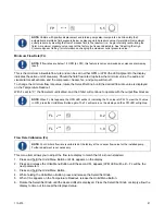
This menu item allows you to adjust the flow rate display to match that of a known standard.
1. Press and hold the Units/Menu Button until HL appears on the display.
2. Press and release the Units/Menu Button until the second FL appears (LPM LED will be lit – Fc will be the
next parameter).
3. Press and hold the Units/Menu Button.
4. While holding the Units/Menu Button, press and release the Select/Set Knob.
5. When CAL appears on the Temperature Readout, release the Units/Menu Button.
6. Rotate the Select/Set Knob until the desired offset is displayed. Press the Select/Set Knob or simply allow the
display to time out to accept the displayed value.
Summary of Contents for DCA203C4
Page 1: ...Operator s Manual DuraChill Air and Water Cooled 2 and 3 HP Chillers 110 275 25 February 2015...
Page 9: ...110 275 8 Rear View Power Switch Power Switch...
Page 36: ...110 275 35 Pump Performance Specifications subject to change without notice...
Page 40: ...110 275 39 Appendix Flow Diagram Air Cooled Chillers...
Page 41: ...110 275 40 Flow Diagram Water Cooled Chillers...
Page 42: ...110 275 41 Wiring Diagram 208 230V 1 Phase Air Cooled Chillers...
Page 43: ...110 275 42 Wiring Diagram 208 230V 380 460V 3 Phase Air and Water Cooled Chillers...


