background image

110-275 

22 


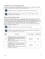
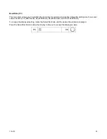
Auto-Refrigeration Temperature (AF) 


NOTE: 

This value is always displayed/set in °C.


This menu item allows you to select the temperature at which refrigeration is activated. When the set point 
exceeds the auto-refrigeration temperature by more than 1.0°C, the cooling and the fan are turned off.   

To change the auto-refrigeration temperature, rotate the Select/Set Knob until the desired value is displayed. 

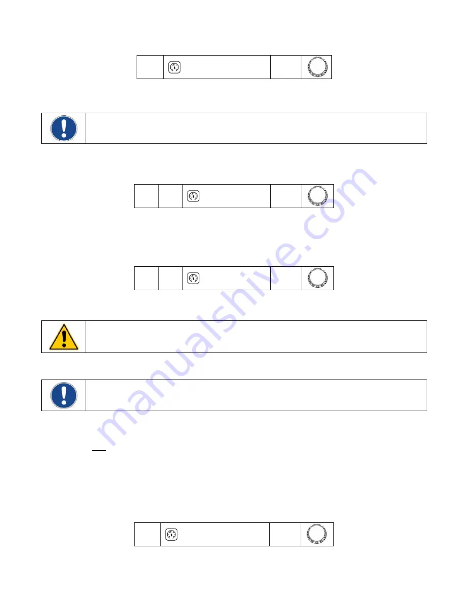
AF 


35


Compressor Band (Cb) 

T

his menu item allows you to set a temperature below set point at which the compressor will turn off. This protects 

the fluid temperature from dropping too low during periods of low or no heat load. The compressor will turn back 
on when the fluid temperature rises above set point.  

Cb 


-06


Calibration Offset (

o

1) 


IMPORTANT:  

To prevent the operator from accidentally changing the calibration offset, a special keystroke 

sequence is required to access this function.


This menu item allows you to adjust the Chiller’s temperature reading to match that of a traceable standard. It 
allows you to offset the displayed temperature value by as much as ±1.9°C.  


NOTE: 

Calibration offset values are always set and displayed in °C.


1.  Press and hold the Units/Menu Button until HL appears on the display.  

2.  Press and release the Units/Menu Button until AP appears on the display. 

3.  Press and hold the Units/Menu Button. 

4.  While holding the Units/Menu Button, press and release the Select/Set Knob.  

5.  When CAL appears on the Temperature Readout, release the Units/Menu Button. The current 

calibration offset value will appear on the Temperature Readout and alternate with the fluid temperature 
reading (allowing you to simultaneously adjust the offset and see the effect on the temperature reading). 

6.  Rotate the Select/Set Knob until the desired calibration offset is displayed. Press the Select/Set Knob or 

simply allow the display to time out to accept the displayed value. 

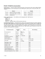
°


0.0


Fc 


0.0


Summary of Contents for DCA203C4

Page 1: ...Operator s Manual DuraChill Air and Water Cooled 2 and 3 HP Chillers 110 275 25 February 2015...

Page 2: ...ctrical Power 14 Optional Signal Inputs Outputs 15 RS 232 RS 485 Serial Output 15 Remote On Off Port 15 Alarm Output 15 Startup 16 Facility Water Flow water cooled units only 16 Filling the Reservoir...

Page 3: ...lectrical Specifications DCA200 Chillers 31 Performance Specifications DCA300 DCW300 Chillers 32 Electrical Specifications DCA300 DCW300 Chillers 33 Pump Performance 35 RS 232 RS 485 Communications 36...

Page 4: ...be configured with a wide variety of standard and optional features including Standard Features Process temperature 41 to 95 F 5 to 35 C Ambient temperature 60 to 95 F 16 to 35 C Temperature stability...

Page 5: ...on the Power Switch indicates that it places the unit in a standby mode It DOES NOT fully disconnect the unit from the power supply Read all instructions pertaining to safety set up and operation Pro...

Page 6: ...ving Always follow your company s procedures and practices regarding safe lifting and relocation of heavy objects WARNING Make sure the equipment s main power switch is in the OFF position before conn...

Page 7: ...tain the container and all packing materials until the unit is completely assembled and working properly Set up and run the unit immediately to confirm proper operation If the unit is damaged or does...

Page 8: ...eservoir Plate Covert Pressure Flow Rate Display Pressure Flow Rate Units Unit Menu Select Button Temperature Display Select Set Knob Power Button Temperature Units Control Panel Air Filter Access air...

Page 9: ...110 275 8 Rear View Power Switch Power Switch...

Page 10: ...ve dust or high room temperatures are present For ease of positioning and maneuverability the Chiller is supplied with casters The front wheels can be locked to keep the Chiller in place while in use...

Page 11: ...of construction should be compatible with the fluid being used as well as the temperature and pressure at which the unit will operate Where applicable always use a back up wrench when making piping co...

Page 12: ...r supply should be connected to the facility water inlet on the Chiller The facility water outlet on the Chiller should be connected to the appropriate return or drain as required The cooling water su...

Page 13: ...is normal 5 Loosen the locknut and then using a flat blade screwdriver adjust the pressure until the reading on the Pressure Flow Rate Display matches the desired maximum operating pressure A clockwi...

Page 14: ...PVC WARNING Do not use caustic corrosive or flammable fluids CAUTION Operation below 15 C 59 F requires antifreeze in the circulation fluid DO NOT use automotive antifreeze as the additives may be har...

Page 15: ...Reservoir has not been filled the pump could be damaged Use the voltage and amperage requirements specified on the identification label on the rear of the Chiller Remove the three screws securing the...

Page 16: ...he instrument enclosure for this connection Remote On Off Port This option allows you to connect a remote on off switch or other remote control device to the Chiller The Chiller is ON when the contact...

Page 17: ...pond by showing standby If there is no response check that the unit is connected to working electrical power and that Power Switch on the rear of the Chiller is in the ON position 2 Press the Power Bu...

Page 18: ...the front panel while returning the Power Switch to the ON position IMPORTANT All user settings except baud rate and calibration offset return to the original factory defaults when the temperature uni...

Page 19: ...displayed value by either pressing the Select Set Knob or allowing the display to timeout Operational parameter limit alarms will shut down the compressor fan pump and heaters Some temperature values...

Page 20: ...ing pressures 10 to 100 PSI 69 to 690 kPa display value x 100 80 PSI 5 5 x 100 550 kPa FL Minimum Flow Rate Minimum allowable flow rate settable in either GPM or LPM Should the fluid flow rate drop be...

Page 21: ...ater fan and pump to turn off To change the low limit value rotate the Select Set Knob until the desired value is displayed LL 0 0 High Ambient Temperature Limit HA NOTE This value is always set in C...

Page 22: ...the desired flow rate value is displayed on the Temperature Readout With FL set to 0 the flow alarm is disabled and the Chiller will continue to operate with the output flow blocked NOTE When FL firs...

Page 23: ...ke sequence is required to access this function This menu item allows you to adjust the Chiller s temperature reading to match that of a traceable standard It allows you to offset the displayed temper...

Page 24: ...Allowable settings are 0 no serial communication 24 2400 baud 48 4800 baud 96 9600 baud and 192 19200 baud To change the displayed setting rotate the Select Set Knob until the desired baud rate is dis...

Page 25: ...es normal operation If this lasts more than 5 seconds fault 16 occurs Lower ambient temperature or raise high ambient temperature limit EHL High temperature set point warning Warning The temperature s...

Page 26: ...g 08 High pressure alarm Alarm Fluid outlet pressure has exceeded the high pressure limit value for over 10 seconds Compressor heater fan and pump are turned off Decrease outlet pressure by removing b...

Page 27: ...ntal changes to set point and other operational values When enabled the values for the following functions can be displayed but not changed Temperature unit Temperature set point Pressure flow rate un...

Page 28: ...dically checked to determine if the fluid level needs to be topped off A sight glass viewing port is provided on the rear left side of the Chiller housing for this purpose Generally fluid should be ad...

Page 29: ...decimal points on Pressure Flow Rate Display Unit in Standby mode Press Power Button on front panel No fluid circulation Insufficient fluid in reservoir Blockage in circulating system Pump is not oper...

Page 30: ...ition while pressing and holding the Select Set Knob The diagnostic menu appears on the Pressure Flow Rate Display the current value for the diagnostic item appears on the Temperature Readout NOTE Dia...

Page 31: ...mperature Stability F C 0 9 F 0 5 C Cooling Capacity 60Hz units 1 Tons Watts BTU hour 1 99 7000 23 885 Cooling Capacity 50Hz units 1 Tons Watts BTU hour 1 75 6160 21 038 Nominal Evaporator Flow 2 US G...

Page 32: ...5 35 29 7 40 40 5 50 44 2 55 DCA204C4 16 4 25 23 6 35 34 4 50 38 1 50 DCA204F 16 8 30 24 35 34 8 50 38 5 50 DCA204G 20 0 30 27 2 40 38 50 41 7 55 DCA206D1 S1 9 5 15 13 1 20 20 3 30 DCA206D2 S2 11 4 17...

Page 33: ...Nominal Evaporator Flow 2 US GPM 6 92 7 46 Refrigerant R134A Pressure PSIG 14 Pump HP 3 4 Fan s HP 2 1 6 N A Condenser Discharge Air Flow CFM 2170 N A Water Condenser Flow Tower Water US GPM N A 9 33...

Page 34: ...A304D6 S6 29 45 36 2 60 47 70 50 7 70 DCA304D7S7 26 6 40 33 8 50 44 6 70 48 3 70 DCA304C3 31 5 50 38 7 60 49 5 70 53 2 70 DCA304C4 25 4 40 32 6 50 43 4 70 47 1 70 DCA304F 25 8 40 33 50 43 8 70 47 5 70...

Page 35: ...45 36 2 60 47 70 50 7 70 DCW306D1 S1 12 8 20 16 4 25 23 6 35 DCW306D2 S2 14 7 25 18 3 30 25 5 35 DCW306D5 S5 11 6 20 15 2 25 22 4 35 DCW306D6 S6 13 4 20 17 25 24 2 35 DCW306D7S7 12 1 20 15 7 25 22 9...

Page 36: ...110 275 35 Pump Performance Specifications subject to change without notice...

Page 37: ...mark indicates that the Chiller could not execute the command either because it was in an improper format or the values were outside the allowable range A response followed by an exclamation point ind...

Page 38: ...isposal and recycling of the equipment from health hazards By doing so you will help to conserve natural and environmental resources and you will ensure that your equipment is recycled in a manner tha...

Page 39: ...in 30 days of receipt of the replacement unit If the defective unit is not received within 30 days the manufacturer reserves the right to bill for the replacement unit If this product requires service...

Page 40: ...110 275 39 Appendix Flow Diagram Air Cooled Chillers...

Page 41: ...110 275 40 Flow Diagram Water Cooled Chillers...

Page 42: ...110 275 41 Wiring Diagram 208 230V 1 Phase Air Cooled Chillers...

Page 43: ...110 275 42 Wiring Diagram 208 230V 380 460V 3 Phase Air and Water Cooled Chillers...

Reviews: