110-275
29
Diagnostic Mode
NOTE:
The Chiller must be set up to display temperature in °C in order to access the diagnostic mode.
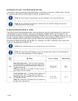
The Chiller incorporates a Diagnostic mode, which displays important operational information that can aid in
troubleshooting. To access the Diagnostic mode, place the Power Switch on the rear of the unit in the OFF
position and then return it to the ON position while pressing and holding the Select/Set Knob. The diagnostic
menu appears on the Pressure/Flow Rate Display; the current value for the diagnostic item appears on the
Temperature Readout.
NOTE:
Diagnostic items are display values only; they cannot be changed..
Menu Item
Description
At
Ambient temperature at front panel
EC
External control
Ut
Upper (head) temperature
Li
Percent of Line voltage
Ct
Chiller type (model)
Fb
Fuse bits (remote control voltage, contact closures, etc.)
03 (variable numeric value)
Fluid flow rate or pressure;
Temperature Display shows current fluid temperature
Summary of Contents for DCA203C4
Page 1: ...Operator s Manual DuraChill Air and Water Cooled 2 and 3 HP Chillers 110 275 25 February 2015...
Page 9: ...110 275 8 Rear View Power Switch Power Switch...
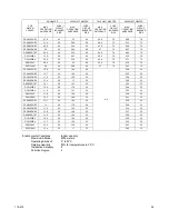
Page 36: ...110 275 35 Pump Performance Specifications subject to change without notice...
Page 40: ...110 275 39 Appendix Flow Diagram Air Cooled Chillers...
Page 41: ...110 275 40 Flow Diagram Water Cooled Chillers...
Page 42: ...110 275 41 Wiring Diagram 208 230V 1 Phase Air Cooled Chillers...
Page 43: ...110 275 42 Wiring Diagram 208 230V 380 460V 3 Phase Air and Water Cooled Chillers...


