background image


Instruction Manual 

DHS-05 & DHS-1 Spreader - V1.4 

www.durapac.com 

Page 4 of 10 


Never pressurise uncoupled couplers. Only use hydraulic equipment in a coupled 
system 

3.2


Hydraulic Hoses & Fluid Transmission Lines 


Avoid short runs of straight line tubing. Straight line runs do not provide for expansion 
and contraction due to pressure and/or temperature changes 


Reduce stress in tube lines. Long tubing runs should be supported by brackets or clips. 
Before operating the pump, connections should be tightened securely and leak-free. 
Over tightening can cause premature thread failure or high pressure fittings to burst 


Should a hydraulic hose ever rupture, burst or need to be disconnected, immediately 
shut off the pump and release all pressure. Never attempt to grasp a leaking 
pressurised hose with your hands. The force of escaping hydraulic fluid can inflict 
injury 


Do NOT

 subject the hose to potential hazard such as fire, sharp objects, extreme heat 

or cold or heavy impact 


Do NOT

 allow the hose to kink, twist, curl, crush, cut or bend so tightly that the fluid 

flow within the hose is blocked or reduced. Periodically inspect the hose for wear 


Hose material and coupler seals must be compatible with the hydraulic fluid used. 
Hoses also must not come in contact with corrosive materials such as battery acid, 
creosote-impregnated objects and wet paint. Never paint a coupler or hose 

FAILURE TO HEED THESE WARNINGS MAY RESULT IN PERSONAL INJURY AS WELL AS PROPERTY DAMAGE. 

4.0


Installation 


IMPORTANT:

 Always secure threaded port connections with high grade, non-hardening pipe 

thread sealant. Teflon tape can be used if only one layer of tape is used and it is applied 
carefully, two threads back, to prevent the tape from being introduced into hydraulic system, 
which could cause jamming of precision-fit parts 

4.1


Familiarise yourself with the specifications and illustrations in this owner’s manual. 
Know your spreader, its limitations and how it operates before attempting to use. Refer 
to the specification chart below or if in doubt, contact a Durapac representative. 


4.2


Make hydraulic connections; use a pump release valve or a 3-way valve and one hose 
for a single-acting cylinder. 


IMPORTANT:

 Fully hand-tighten all couplers. Loose coupler connections will block 

the flow of oil between the pump and the spreader 

4.3


Check all system fittings and connections to be sure they are tight and leak free. 

DHS-05

0.5

9.5

13

90

1.9

DHS-1

1.0

14.0

12

99

2.2

Weight 

(kg)

Model

Number

Capacity 

(ton)

Oil Capacity 

(cc)

Tip Clearance 

Min. (mm)

Spread Max. 

(mm)

Summary of Contents for DHS-05

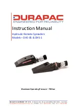
Page 1: ... LTD 2 186 Granite Street GEEBUNG QLD 4034 Australia sales absoluteequipment com au Phone 61 7 3865 4006 Fax 61 7 3102 6288 Maximum Operating Pressure 700 bar Instruction Manual Hydraulic Remote Spreaders Models DHS 05 DHS 1 ...

Page 2: ...spreader that has been or suspected to have been subject to a shock load should be removed from service immediately until inspected by a Durapac authorised service centre Owners and operators of this equipment should be aware that the use and subsequent repair of this equipment may require specialised training and knowledge 3 0 Safety Save these instructions For your safety read and understand the...

Page 3: ...equipment must only be serviced by a qualified hydraulic technician For repair service contact the Durapac authorised service centre in your area To protect your warranty use only high quality hydraulic oil CAUTION KEEP HYDRAULIC EQUIPMENT AWAY FROM FLAMES AND HEAT Hydraulic fluid can ignite and burn Excessive heat will soften packings and seals resulting in fluid leaks Heat also weakens hose mate...

Page 4: ... seals must be compatible with the hydraulic fluid used Hoses also must not come in contact with corrosive materials such as battery acid creosote impregnated objects and wet paint Never paint a coupler or hose FAILURE TO HEED THESE WARNINGS MAY RESULT IN PERSONAL INJURY AS WELL AS PROPERTY DAMAGE 4 0 Installation IMPORTANT Always secure threaded port connections with high grade non hardening pipe...

Page 5: ...noted For complete operating instructions refer to the instruction sheet included with each pump The DHS 05 and DHS 1 spreaders have a spring return cylinder and the speed of retraction is affected by the length of the hose and other restrictions in the line Most 700 bar hand or power pumps for use with single acting tools are compatible with the DHS 05 and DHS 1 spreaders 5 1 Ensure that both spr...

Page 6: ...tions Dirt sand etc will quickly ruin any hydraulic system Ensure that couplings are clean and free of foreign matter After each use clean couplings and attach dust caps Maintenance is required when wear or leakage is noticed Periodically inspect all components to detect any problem that may require service and maintenance 6 1 Check for loose connections and leaks 6 2 Replace damaged parts immedia...

Page 7: ...n pump release valve Loose couplers Tighten couplers Blocked hydraulic lines Clean and flush lines Weak or broken retraction springs Send to a Durapac authorised service centre for repair Internally damaged cylinder Send to a Durapac authorised service centre for repair Pump reservoir too full Drain hydraulic fluid to correct level Erratic Action Air in system or pump cavitation Add fluid bleed ai...

Page 8: ...em Load is above the capacity of the system Use the correct equipment Sticking or binding cylinder Check for dirt or leaks Check for bent misaligned worn parts or defective packings Spreader moves slower than normal Loose couplers Tighten couplers Restricted hydraulic line or fitting Clean Replace if damaged Pump not operating correctly Check pump s operating instructions Repair or replace as nece...

Page 9: ...preader base ZAL1631 1 2 Spreader jaw ZAL1632 1 3 Spring ZAL1633 1 4 Pin ZAL1626 1 5 Circlip ZAL1628 1 6 Piston rod ZAL1634 1 7 Back up ring ZAL1635 1 8 Cup seal ZAL1636 1 9 O ring ZAL1637 1 10 Cylinder ZAL1638 1 11 Coupler ZAL1472 1 Seal kit ZAL1639 1 Items marked with a are contained within a standard seal kit Serial model and part numbers need to be quoted when ordering parts ...

Page 10: ...ted as a convenient reference of location and position in the assembly sequence Item Description Qty 1 Spreader jaw upper 1 2 Spring pin 2 3 Return spring inner 1 4 Return spring outer 1 5 Spreader base 1 6 Spreader jaw axle 1 7 Spring clip 1 8 O ring 1 9 Back up ring 1 10 Piston rod 1 11 O ring 1 12 Piston rod saddle 1 13 Coupler spreader 1 14 Coupler cap 1 15 Dust cover 1 ...

Reviews: