24
1 1 5 0 / 1 1 5 5 H A Y B U S T E R T U B G R I N D E R O P E R A T I N G I N S T R U C T I O N S
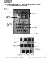
2.11 1150/1155 Haybuster Tub Grinder Electronic Engine Controls
(S.N. Up To 23‑2‑GJ‑0190)
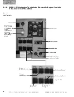
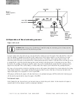
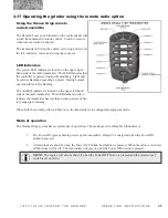
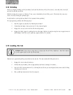
figure 2.5
control panel
Key switch
Multi gage
Quad gauge
Fuel gauge
Job hours gauge
Grinding hours
gauge
Job hours reset
button
Rotor status
lights
Electronic
governor
Conveyor circuit
hydraulic pressure
gauge
Rotor engage
button - hold in for
approximately 30
seconds
Rotor disengage
button - push in
to disengage fluid
coupler
(yellow in color)
Tub circuit
hydraulic
pressure
Auxiliary hydraulic
pressure gauge
Conveyor
Fold/Unfold
Tub Up/Down
Lights On/Off
Conveyor
Up/Down
Conveyor pivot
Right/Left
Remote radio/
Local switch
Tub rotation
Forward/Reverse
Conveyor
On/Off
Engine kill switch
(red in color)
Throttle toggle
Optional hay guide
Scroll switch
2.11.1 Control panel
The control panel is located on the left hand side of the en-
gine. Controls on the control panel include; engine start,
emergency kill switch, throttle, tub controls, conveyor on/off,
conveyor positioning, rotor engage button, rotor disengage
button, tub governor, tub tilt, and the job hours reset button.
Gauges on the control panel include; tub circuit hydraulic
pressure, conveyor hydraulic pressure, auxiliary hydraulic
pressure, fuel level, grinding hours gauge, job hours gauge,
and a quad guage with engine oil pressure, battery, engine
temperature and fuel level, and a multi gauge.
Hour meter
Panel lites
Yellow warning lite
Red warning lite


