33
1 1 5 0 / 1 1 5 5 H A Y B U S T E R T U B G R I N D E R O P E R A T I N G I N S T R U C T I O N S
3.9 Operation of the electronic governor
Engine (Auto) mode
IMPORTANT:
Except when calibrating or trouble shooting the electronic governor always use the
engine (auto) mode of the electronic governor.
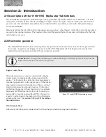
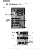
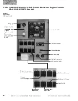
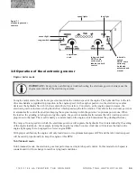
figure 3.1
electronic governor
controls
sensor light
range switch
engine load
knob
tub speed knob
NOTE: some
units may be
labeled tub limit
control
speed lights
fuse light
In engine (auto) mode, the electronic governor monitors the rotation speed of the engine. The hydraulic flow to the tub
drive mechanism is regulated in proportion to the engine speed. As the engine speed slows, the electronic governor
decreases the hydraulic flow which slows down the tub’s rotation. Conversely, as the engine speed increases, the
electronic governor increases the hydraulic flow which speeds up the tub’s rotation. This allows the electronic governor
to automatically control the feed rate keeping the engine running within the governor’s optimum power zone. When
the load on the grinding rotor begins to lug the engine, the governor automatically reduces the tub’s rotation speed in
proportion to the load. The result is nearly a constant load on the engine, which maximizes the grinding efficiency.
The range of rotor speeds for which the electronic governor will regulate the hydraulic flow is determined by the setting
of the engine load knob. For example, turning the engine load knob counter clockwise will increase the load on the
engine by keeping the tub engaged to a lower engine RPM.
With proper calibration, the engine will only load down to its optimum horsepower RPM, and the tub’s rotation speed
will be varied proportionally to keep the engine at this RPM.
Tub (Manual) mode
In tub (manual) mode, the electronic governor performs as a simple tub speed control. In this mode the tub speed is
constant and it will not change to match varying load conditions.
tub mode
switch
NOTE: some
units may
be labeled
automatic and
manual


